39 negative edge triggered jk flip flop timing diagram
Negative Edge Triggered Flip-Flops: Basic Electronic Knowledge Negative Edge Triggered: Low-level triggering Contrarily, low-level triggering is applicable in low-state flip-flops. Also, apart from checking the clock input lead, you can examine a low state indicator bubble. Low-level triggering Negative Edge Triggered:Positive edge triggering Solved a) Complete the following timing diagram for a | Chegg.com Question: a) Complete the following timing diagram for a negative edge triggered JK flip-flop. Assume Q (0*)=0. Clock J K Q b) Complete the following timing diagram for a positive edge triggered T flip-flop with an asynchronous active low PreN input. Assume Q (0*)=1. Clock PreN T This problem has been solved! See the answer
Answered: 1. Design a MOD 5 counter using a… | bartleby Question. 1. Design a MOD 5 counter using a negative edge triggered JK flip flops and draw the resulting timing diagram. Transcribed Image Text: Design a synchronous MOD 5 counter using a negative edge triggered JK flip flops and draw the resulting timing diagram.

Negative edge triggered jk flip flop timing diagram
2. Explain the 4 bit ripple counter and also draw a timing diagram. holding the least significant bit receives the incoming count pulses. The diagram of a 4-bit binary ripple All J and K inputs are equal to 1. Fig: 4-bit ripple counter using JK Flip Flop The small circle in the CP input indicates that the flip-flop complements during a negative-going transition or when the output to which it is connected goes Timing Diagram for A Negative Edge Triggered Flip Flop - YouTube via YouTube Capture Flip Flop Triggering-HIGH,LOW,POSITIVE,and NEGATIVE Edge Triggering Negative Edge Triggering. When a flip flop is required to respond during the HIGH to LOW transition state, a NEGATIVE edge triggering method is used.. It is mainly identified from the clock input lead along with a low-state indicator and a triangle. Take a look at the symbolic representation shown below. Negative Edge Triggering.
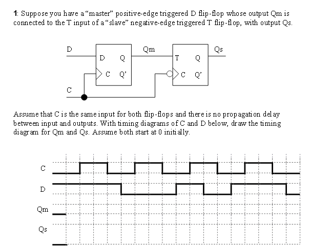
Negative edge triggered jk flip flop timing diagram. Master Slave Flip Flop | Circuit Diagram and Timing Diagram with 10 ... The output of the flip flop changes at high or low input, i.e., level triggered. Master-slave JK flip flop can be used in both triggered ways; in edge-triggered, it can be +ve edge-triggered or -ve edge triggered. In edge-triggered, the master flip flop is derived from the +ve edge of the clock pulse. At that time, the slave flip flop is in the ... 3 bit Synchronous Down Counter - GeeksforGeeks Therefore, Flip flop 3 output is toggle when there is clock falling edge and Q'2=1 and Q'1 = 1 .(as you can see from timing diagram) Therefore, we get output(as down counting Q3(MSB) Q2 Q1(LSB) after 8th -ve edge triggered clock the output of the three Flip flops again becomes Q3 = 0, Q2 = 0, Q1 =0. PDF Edge-triggered Flip-Flop, State Table, State Diagram • Edge-triggered: Read input only on edge of clock cycle (positive or negative) • Example below: Positive Edge-Triggered D Flip-Flop • On the positive edge (while the clock is going from 0 to 1), the input D is read, and almost immediately propagated to the output Q. Only the value of D at the positive edge matters. D C S C R D Clock Q Q Edge-triggered Latches: Flip-Flops - All About Circuits The symbols above are positive edge-triggered: that is, they "clock" on the rising edge (low-to-high transition) of the clock signal. Negative edge-triggered devices are symbolized with a bubble on the clock input line: Both of the above flip-flops will "clock" on the falling edge (high-to-low transition) of the clock signal. REVIEW:
1. Complete the timing diagrams for, a. A negative edge-triggered... 1. Complete the timing diagrams for, a. A negative edge-triggered... 1. Complete the timing diagrams for, a. A negative edge-triggered J-K flip-flop, and b. A positive-edge triggered J-K flip-flop. Assume initial output to be 1. Engineering & Technology Electrical Engineering ECE 102. flipflop - JK flip-flop timing diagram positive edge triggering ... I'll consider the following JK-flip flop truth table. Let's analyze it for each clock edge. CLK edge 1: The output was initially zero (or to be precise, high impedance) and at edge1, INPUT = J = 0. So, the output should be zero in this clock cycle. CLK edge 2: The output in the previous cycle was zero and INPUT= 0 at edge2. flip flop timing diagram - Wiring Diagram and Schematics 14 An Example Timing Diagram For A Rising Edge Triggered D Flip Flop Scientific. Pengertian Dan Macam Rangkaian Flip Flop Katakoala. Flip flops and latches northwestern jk flop proposed ndr based cml d macam rangkaian tipe diagram sirkuit dan jenis jenisnya binus circuits worksheet digital sequential logic for the following master slave ... JK Flip-Flop - PRESET & CLEAR Inputs - Truth Table - Electronics Area The JK Flip-Flop is a sequential device with 3 inputs (J, K, CLK (clock signal)) and 2 outputs (Q and Q'). J and K are control inputs. These control inputs are named "J" and "K" in honor of their inventor Jack Kilby. JK Flip-Flop is called as a universal Flip-Flop or a programmable flip-flop because using its J and K inputs, the other ...
JK Flip-Flop Circuit Diagram, Truth Table and Working Explained JK Flip-flop Circuit diagram and Explanation: The IC power source V DD ranges from 0 to +7V and the data is available in the datasheet. Below snapshot shows it. Also we have used LED at output, the source has been limited to 5V to control the supply voltage and DC output voltage. We have used a LM7805 regulator to limit the LED voltage. D Type Flip Flop: Circuit Diagram, Conversion, Truth Table The negative edge D flip-flop can be represented with a triangle and a bubble at the clock end of the D flip-flop block diagram. Negative Edge Triggered D flip flop Circuit Diagram The -ve edge D flip flop can be designed by adding a -ve edge detector circuit with the clock pulse. The -ve edge detector detects the -ve edge of the clock pulse. JK Flip Flop Truth Table and Circuit Diagram - Electronics Post The inputs labeled J and K are the data inputs ( which used to be S and R inputs in S-R Flip-flop). The input labeled CLK is the clock input. Outputs Q and Q' are the usual normal and complementary outputs . The circuit diagram of the J-K Flip-flop is shown in fig.2 . Fig.2 Solved Complete the timing diagram of the shown negative | Chegg.com Electrical Engineering questions and answers. Complete the timing diagram of the shown negative edge triggered JK Flip Flop. Suppose PR & CLR are connected to Vcc PR 3 Q Timing diagram for JK Flip-flop Negative Edge Triggered - CLK clock K ह lo CLR Fig 10.1 JK Flip Flop K. Question: Complete the timing diagram of the shown negative edge ...
Asynchronous Up counter for Positive & Negative edge-triggered flip-flops Now, let's discuss the circuit operation and timing diagram of the Asynchronous Up counter for Negative edge-triggered flip-flops. Figure2.2: Timing diagram of 4-bit asynchronous binary Up counter for negative edge triggered F/Fs. From the above timing diagram (figure 2.2) it is clear that this 4-bit asynchronous counter counts upwards.
Edge-triggered D flip-flops: A timing diagram Slide 3 of 7
How does a negative edge-triggered JK flip-flop work? - Quora Inside the flip flop, you have a High Pass filter ( CR circuit) and diode combination that converts the clock pulse to the edges. Here only the negative edge is chosen, the positive edge eliminated by using the diode.The circuit inside is designed to get its input during that small edge. Balajee Seshadri
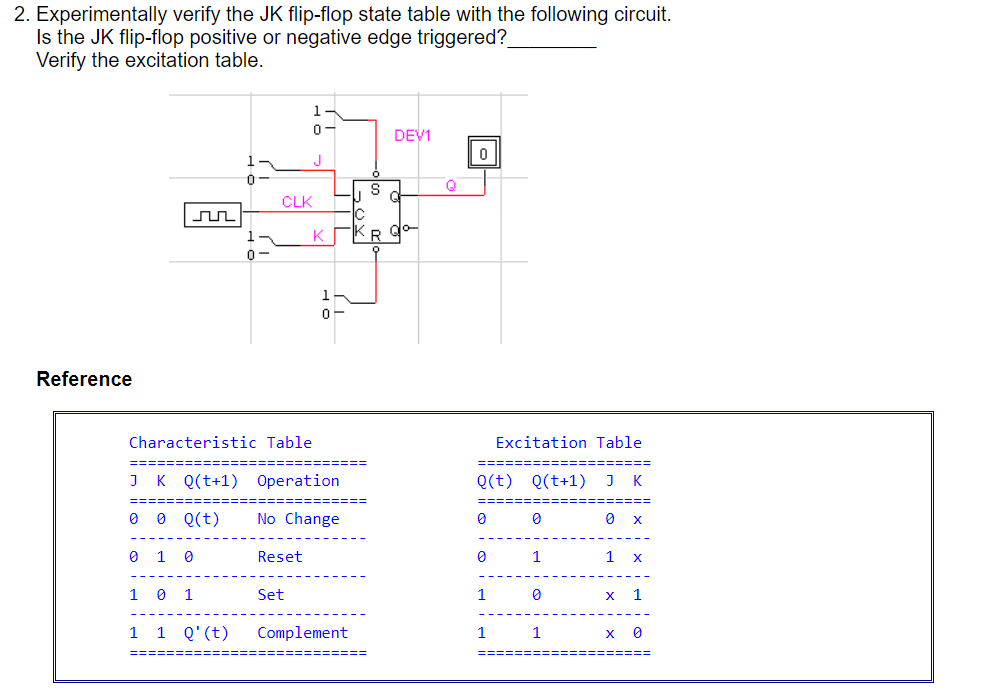
Model a negative-edge-triggered J-K flip-flop - Simulink Description The J-K Flip-Flop block models a negative-edge-triggered J-K flip-flop. The J-K flip-flop block has three inputs, J , K, and CLK. On the negative (falling) edge of the clock signal ( CLK ), the J-K Flip-Flop block outputs Q and its complement, !Q, according to the following truth table.
Jk Flip Flop Timing Diagram - schematron.org The JK flip-flop has two inputs, labeled J and K. J corresponds The timing diagram for the negatively triggered JK flip-flop. The standard symbol for the J-K FF is shown in view A of figure Figure - J-K flip-flop: A. Standard symbol; B. Truth Table; C. Timing diagram.
JK Flip-flops - Learn About Electronics A theoretical schematic circuit diagram of a level triggered JK master slave flip-flop is shown in Fig 5.4.3. Gates G1 and G2 form a similar function to the input gates in the basic JK flip-flop shown in Fig. 5.4.1, with three inputs to allow for feedback connections from Q and Q.. Gates G3 and G4 form the master flip-flop and gates G7 and G8 form the slave flip-flop.
JK Flip Flop: What is it? (Truth Table & Timing Diagram) Initially let J = K = 0, Q = 0 and Q̅ = 1. Now consider the appearance of positive-edge of the first clock pulse at the CLK pin of the flip-flop. This results in X 1 = 0 and X 2 = 0. Then the output of N 1 will become 0 as X 1 = 0 and Q̅ = 1; while the output of N 2 will become 1 as X 2 = 0 and Q = 0. Thus one gets Q = 0 and Q̅ = 1.
Flip-Flops and Latches - Northwestern Mechatronics Wiki The timing diagram for the negatively triggered JK flip-flop: Latches. Latches are similar to flip-flops, but instead of being edge triggered, they are level triggered.. The most common type of latch is the D latch.While CK is high, Q will take whatever value D is at. When CK is low, Q will latch onto the last value it had before CK went low, and hold it until CK goes high again.


0 Response to "39 negative edge triggered jk flip flop timing diagram"
Post a Comment