37 step up transformer diagram
What is Isolation Transformer? Definition, Theory & Diagram The conventional two winding step-up and step-down transformers can provide the electrical isolation between their primary and secondary circuits. The only difference between the conventional two winding transformer and the isolation transformer is that the isolation transformer is a 1:1 transformer (i.e. with N 1 = N 2 ) and is used only for ... Step-Up Transformers | McMaster-Carr Enclosed Step-Up/Step-Down AC to AC Transformers Improve the efficiency of your equipment— wire these transformers to step your input voltage up or down by as much as 20%. Choose an input/output voltage combination that comes closest to matching your application, then choose the power output (in VA) of the equipment you want to operate.
› transformerTransformer - Electrical4U Dec 27, 2018 · Open Delta Connection of Transformer: Calculation, Formula And Diagram (V-V Connection) June 9, 2019 April 18, 2021 Single Three Phase Transformer vs Bank of Three Single Phase Transformers
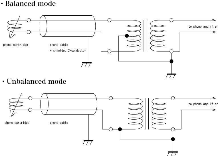
Step up transformer diagram
› build-a-transformerBuild a Transformer | AC Circuits | Electronics Textbook Wrap two, equal-length bars of steel with a thin layer of electrically-insulating tape. Wrap several hundred turns of magnet wire around these two bars. You may make these windings with an equal or unequal number of turns, depending on whether or not you want the transformer to be able to “step” voltage up or down. Step-up and Step-down Transformers | Transformers ... Step-down transformer: (many turns :few turns). The step-up/step-down effect of coil turn ratios in a transformer is analogous to gear tooth ratios in mechanical gear systems, transforming values of speed and torque in much the same way: Torque reducing gear train steps torque down, while stepping speed up. TRANSFORMERS - Applied Industrial Electricity The step-up/step-down effect of coil turn ratios in a transformer is analogous to gear tooth ratios in mechanical gear systems, transforming values of speed and torque in much the same way: Figure 8.4 Torque reducing gear train steps torque down, while stepping speed up.
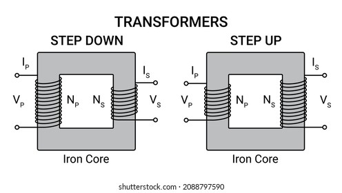
Step up transformer diagram. Transformer Circuit Diagram - U Wiring The equivalent circuit diagram of transformer is given below-Where R 1 Primary Winding Resistance. The transformer works on the principle of Faradays law of electromagnetic induction and mutual induction. 14 Schematic Diagram Of Transformer. Figure 2 delta delta transformer connections click to expand diagram. Working Principle of a Transformer. Step Down Transformer: Definition, Diagram & Working ... A step-down transformer is a type of transformer that converts the high voltage (HV) and low current from the primary side of the transformer to the low voltage (LV) and high current value on the secondary side of the transformer. The reverse of this is known as a step up transformer. A transformer is a type of static electrical equipment that ... towardsdatascience.com › illustrated-guide-toIllustrated Guide to Transformers- Step by Step Explanation ... Apr 30, 2020 · The next step is to inject positional information into the embeddings. Because the transformer encoder has no recurrence like recurrent neural networks, we must add some information about the positions into the input embeddings. This is done using positional encoding. The authors came up with a clever trick using sin and cosine functions. Transformer - Definition, Types, Working Principle, Diagram The step-up transformer will decrease the output current and the step-down transformer will increase the output current for keeping the input and the output power of the system equal. The transformer is basically a voltage control device that is used widely in the distribution and transmission of alternating current power.
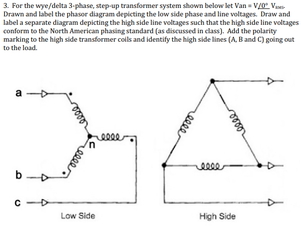
Difference Between Step-up and Step-down Transformer ... Step-up transformer extends the voltages from 220v-11kv or above, whereas, step-down transformer reduces the voltages from 440-220v,220-110v or 110-24v,20v,10vetc. Point to Remember: The Same transformer can be used as a step-up or a step-down transformer. It depends upon the ways in which it is connected in the circuit. 3 Phase Stepup Transformer 240 To 480 Wiring Diagram ... 3 Phase Stepup Transformer 240 To 480 Wiring Diagram - Wiring Diagram is the graphical depiction of a intricate electric circuit. It stands for the physical parts of the electric circuit as geometric forms, with the actual power and connection connections in between them as slim edges. electrical-engineering-portal.com › zigzagZigZag Transformer Connection Overview - EEP Feb 06, 2020 · Therefore, the transformer allows the three in-phase currents to easily flow to neutral. If three currents, equal in magnitude but 120° out of phase with each other, are applied to the three terminals, the ampere-turns in the windings cannot cancel and the transformer restricts the current flow to the negligible level of magnetizing current. 480v To 120v Control Transformer Wiring Diagram - easywiring 480v to 240v transformer wiring diagram 240v to 480v step up transformer wiring diagram 480v 3 phase to 240v single phase transformer wiring diagram 480v to 240v 3 phase transformer wiring diagram every electric arrangement is composed of various unique components. This will convert the starter from common control to separate control. 240 x 480 ...
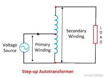
Autotransformer-Working Diagram,advantages, disadvantages The above diagram depicts the connections of the loaded step-down and step-up autotransformer. In both cases, I 1 is the input current and I 2 is output current, Regardless of Step Up/Stepdown autotransformer, the current in the section of winding that is common to both the primary and secondary is the difference between these two currents I 1 ... › step-up-Step Up Transformer: Definition, Diagram & Working Principle ... A step-up transformer is a type of transformer that converts the low voltage (LV) and high current from the primary side of the transformer to the high voltage (HV) and low current value on the secondary side of the transformer. The reverse of this is known as a step down transformer. A transformer is a piece of static electrical equipment ... 3 Phase 480 To 240 Transformer Wiring Diagram - easywiring All of the open style seem to be 120 or 240 on secondary but never both voltages on secondary. 480v 3 phase transformer wiring diagram step down tags to 120v. None x4x1 h4 h3 h2 h1 x2x3 primary. 3 phase step up transformer 240 to 480 wiring diagram wiring diagram is a simplified pleasing pictorial representation of an electrical circuit. 480v 3 Phase To 120/240v Single Phase Transformer Wiring ... Step up transformer wiring diagram full 3 phase 240 to 480 schemes basics information guide three power distribution configurations with motor transformers and how wire a multi tap 4 wye single. Taps 5 per step. For volt primary to volt secondary degree temperature rise units the dimensional information shipping weight lbs wiring diagram number.
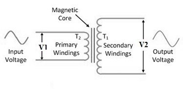
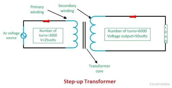
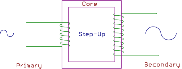
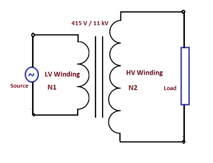
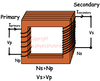
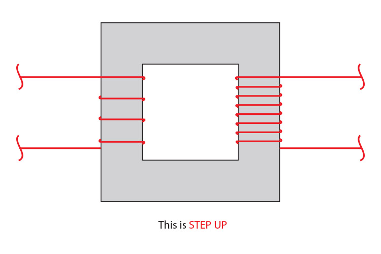
Step Up Transformer : Construction, Working & Its Applications The Step-up transformer diagram is shown below. The construction of the step-up transformer can be done using core and windings. Core The designing of core in the transformer can be done using a high permeable material. This core material allows the magnetic flux to flow with less loss.
Step-up and step-down transformers in the transmission of ... A step-up transformer. beside the power station to step-up the voltage and consequently step-down the current reducing electrical energy wasted as heat energy in the overhead cables. Electricity ...
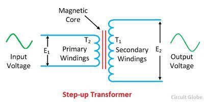
What is a Step-up & a Step-down Transformer? Definition ... Considered a step-up transformer shown in the figure below. The E 1 and E 2 are the voltages, and T 1 and T 2 are the number of turns on the primary and secondary winding of the transformer.. The number of turns on the secondary of the transformer is greater than that of the primary, i.e., T 2 > T 1.Thus the voltage turn ratio of the step-up transformer is 1:2.
480v To 208v Transformer Wiring Diagram Transformer wiring diagrams are printed on the . ings are shown connected to form a V delta to /V wye, 3-phase, step-down transformer bank. The installation of transformers is one of the most common, yet complicated V delta primary to a /V 3-phase wye secondary transformer in a new.
Draw a labelled diagram of a stepup transformer Obtain ... Complete step by step solution: First of all, we will draw the circuit diagram of the transformer as, Where, subscripts P and S denote the primary (input) and secondary (output) windings and E denotes the induced voltage across the winding. Let's assume that the connecting wires are ideal, that is the voltage drop across the connecting wire ...
Step-Down Transformer: Application and Working Principles Diagram for step-up and step-down transformer. (Reference: electronicshub.org) The turn ratio determines the ratio of the voltage in a transformer. By using a larger number of turns in the winding, we will have a higher produced voltage in it. A step-down transformer has a lesser amount of turns on secondary to make a low voltage and more turns ...
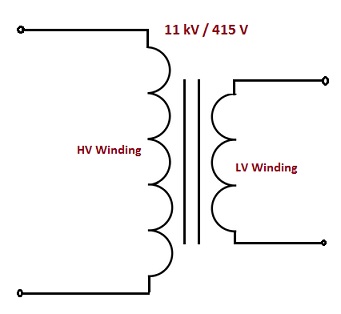
Step Up Transformer : Working, Construction, Benefits and Uses The step up transformer diagram is Step Up Transformer Diagram Theoretically, a transformer can be functioned as both step-up and step-down and is based on the direction of energy flow. When compared with LV windings, HV windings are more whereas the cross-sectional area of LV winding is more than HV. This is because LV windings hold more current.
Three Phase Transformer Connections and Basics In a delta connected ( Dd ) group of transformers, the line voltage, V L is equal to the supply voltage, V L = V S.But the current in each phase winding is given as: 1/√ 3 × I L of the line current, where I L is the line current. One disadvantage of delta connected three phase transformers is that each transformer must be wound for the full-line voltage, (in our example above 100V) and for ...
3 Phase Step Up Transformer 240 To 480 Wiring Diagram ... About diagram 3 phase 480 wiring to transformer 240. Transformer has frequency rating of 60 hz and power rating of 30 kva. 3 phase 3 wire and phase to neutral 45°. A 10 kva transformer, / volt secondary is to service an 8 kva. 3 ct coil and amp testing meters are shown. You can also choose from three, single step up transformer 3 phase 240 to ...
Step Up Transformer - Working, Construction, Applications ... A Step Up Transformer has been explained in a more detailed manner with a schematic diagram as shown in Fig. 4. Here V 1 and V 2 are the input and output Voltages respectively. T1 and T2 are the Turns on the Primary and the Secondary windings.
Auto transformer - Theory, Diagram, Advantages ... An auto transformer is a transformer having only one winding wound on a laminated magnetic core, the part of this winding being common to both the primary and secondary circuits. As an ordinary two winding transformer, it can be used as a step-down or a step-up transformer as illustrated in Figs. 1 (a) and (b) respectively. In Fig. 1 (a), the ...
PDF Electrical Connection Diagrams Acme Transformer Design Figures ACME ELECTRIC U MILWAUKEE, WI U 800.334.5214 U acmetransformer.com 125 GENERALGENERAL ELECTRICAL CONNECTION DIAGRAMSACME® TRANSFORMER™ WIRING DIAGRAMS PRIMARY: 240 Volts Delta SECONDARY: 208Y/120 Volts TAPS: 2, 5% BNFC X1 H1 X2 X3 H2 H3 X0 3 2 1 3 2 1 3 2 1 ConnectConnect Primary Primary Inter- Secondary
Step Up Transformer: Construction & Working Principles ... The Construction of a step up transformer is very simple. The step up transformer diagram has some main parts. This construction can be performed using core and windings. Click here to see the construction of this instrument completely. Core The modeling of the core in the transformer can be performed employing a high permeable substance.
STEP UP TRANSFORMER CONNECTION DIAGRAM - YouTube It means that primary side is connected in delta and secondary side is connected in star. Most commonly delta-star connection is used as a step up transforme...
electrical-engineering-portal.com › learn-toLearn To Interpret Single Line Diagram (SLD) | EEP Nov 22, 2021 · Attached to the drawout circuit breaker (b1), a step-down transformer is used to take the voltage in that area of the system from 15kV down to 5kV. SLD area B On the 5kV side of this transformer, a disconnect switch is shown.
goodcalculators.com › venn-diagram-makerVenn Diagram Maker | Good Calculators You can use this simple Venn Diagram Maker to generate symmetric Venn diagrams from a given set of data and compute the intersections of the lists of elements. You can also use the Venn Diagram Maker to export snapshots of the Venn diagrams in the form of image files. The Venn Diagram Maker can process up to six lists of elements.
TRANSFORMERS - Applied Industrial Electricity The step-up/step-down effect of coil turn ratios in a transformer is analogous to gear tooth ratios in mechanical gear systems, transforming values of speed and torque in much the same way: Figure 8.4 Torque reducing gear train steps torque down, while stepping speed up.
Step-up and Step-down Transformers | Transformers ... Step-down transformer: (many turns :few turns). The step-up/step-down effect of coil turn ratios in a transformer is analogous to gear tooth ratios in mechanical gear systems, transforming values of speed and torque in much the same way: Torque reducing gear train steps torque down, while stepping speed up.
› build-a-transformerBuild a Transformer | AC Circuits | Electronics Textbook Wrap two, equal-length bars of steel with a thin layer of electrically-insulating tape. Wrap several hundred turns of magnet wire around these two bars. You may make these windings with an equal or unequal number of turns, depending on whether or not you want the transformer to be able to “step” voltage up or down.
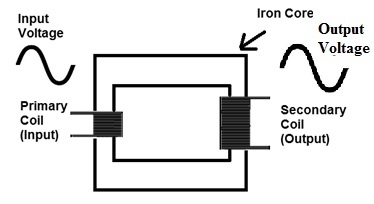
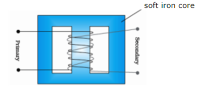


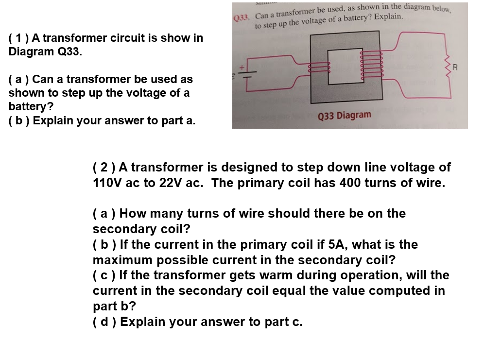










0 Response to "37 step up transformer diagram"
Post a Comment