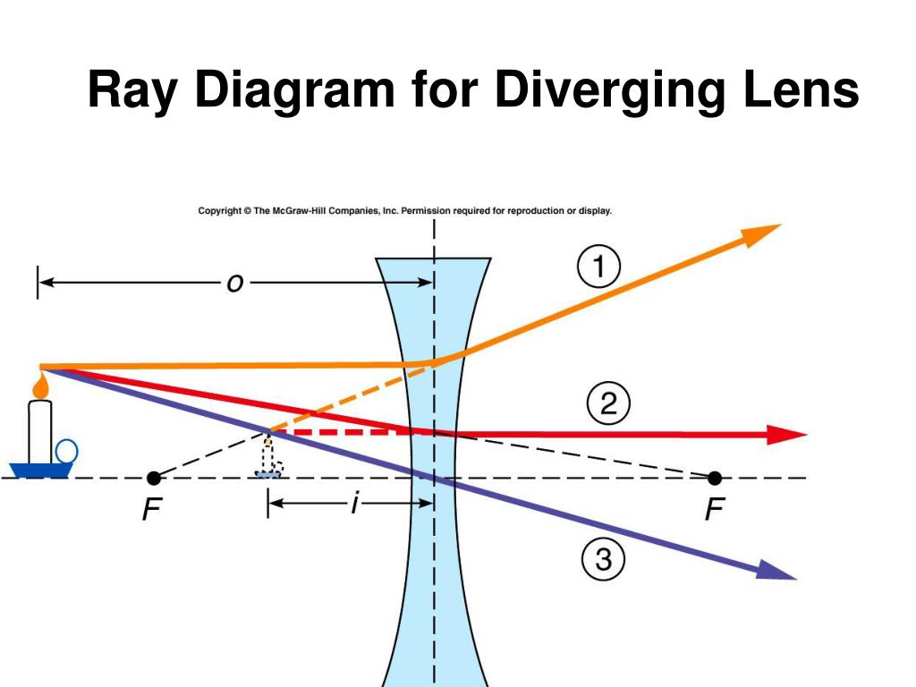
43 ray diagram for diverging lens
Diverging lens - interactive simulations - eduMedia A diverging lens always form an upright virtual image. Ray diagrams are constructed by taking the path of two distinct rays from a single point on the object: A ray passing through the center of the lens will be undeflected. A ray proceeding parallel to the principal axis will diverge as if he came from the image focal point F'. Ray Diagrams for Diverging Lenses - Physics Classroom The Physics Classroom » Curriculum Corner » Refraction and Lenses » Ray Diagrams for Diverging Lenses The document shown below can be downloaded and printed. Teachers are granted permission to use them freely with their students and to use it as part of their curriculum. Visit the Usage Policy page for additional information.
Physics Tutorial: Refraction and the Ray Model of Light Since the three refracted rays are diverging, they must be extended behind the lens in order to intersect. Using a straight edge, extend each of the rays using dashed lines. Draw the extensions until they intersect. All three extensions should intersect at the same location. The point of intersection is the image point of the top of the object.

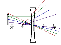
Ray diagram for diverging lens
› class › refrnPhysics Tutorial: Refraction and the Ray Model of Light Previously in Lesson 5, ray diagrams were constructed in order to determine the location, size, orientation, and type of image formed by double concave lenses (i.e., diverging lenses). The ray diagram constructed earlier for a diverging lens revealed that the image of the object was virtual, upright, reduced in size and located on the same side ... Ray Diagrams for Lenses - Wolfram Demonstrations Project This Demonstration lets you visualize the ray diagrams for converging and diverging lenses. By manipulating the object and lens locations, you can create real or virtual images. The rays parallel to the principal axis and the ray through the center of the lens are drawn. [more] Contributed by: Ernest Lee (November 2007) PhysicsLAB: Ray Diagrams for Diverging Lenses Each case will use the three rays outlined in the lesson on diverging lenses where you are provided with an animated gif to show you how the image is formed. First watch each animation, then draw your own diagram. Keep your three rays color-coded - that is, let ray #1 be the same color in each diagram, similarly with ray #2 and ray #3.
Ray diagram for diverging lens. Thin Lenses Calculator - herramientasingenieria.com Real images occur when objects are placed outside the focal length of a converging lens (s>f). If the lens is converging but the distance from the object to the lens is smaller than the focal length, the image will be virtual. Diverging lenses always produce virtual images. This calculator shows a ray diagram when the image is real. Magnification Ray diagrams for the thin lens « bywaysandbinoculars To discuss that of virtual image at finite distance we draw a ray diagram as in the following figure. the object is now between the optical centre and the principal focus. Fig 2. Ray diagram for converging lens: real object, virtual image. We show two rays from the top of the object, an arrow at O. PDF Spherical lenses: converging, diverging Plane mirrors ... Ray diagram for converging lens. Ray 1 is parallel to the axis and refracts as if from F. Ray 2 heads towards F' before refracting parallel to the axis. Ray 3 passes straight through the center of the lens. image is always virtual, upright and reduced O F I F' Ray diagram for diverging lens Two Converging Lens Ray Diagram - schematron.org Examples are given for converging and diverging lenses and for the cases where the The third ray is not really needed, since the first two locate the image. 2) A ray that (seems to) pass (es) through F', will end up parallel to the principal axis. 3) A ray that passes through the center of the lens, will continue virtually.
Ray diagrams for diverging lenses - YouTube Description of how to draw ray diagrams for diverging lenses for grade 10 science. PDF Tutorial: Ray Diagram for Concave Lenses Here we describe the method of drawing a ray diagram for aconcave (diverging) lens for which the object is located beyond the 2F point of the lens. 1. Pick a point on the top of the object and draw three incident rays traveling towards the lens. a. Draw a ray so that it travels toward the focal point on the opposite side of the lens. › 10839 › 3118Concave Lens - Ray diagram, Images Formed - with Steps - Teachoo Apr 26, 2020 · For a Concave lens,There are only 2 casesThey areObject is Placed at InfinityObject is Placed between Infinity and Optical CenterCase 1 - Object is Placed at infinityIn this Case, Object is kept far away from mirror (almost at infinite distance)So, we draw rays parallel to principal axisSince ray pa Lenses - Boston University Lenses 7-26-00 Sections 23.9 - 23.10 Ray diagram for a diverging lens. Consider now the ray diagram for a diverging lens. Diverging lenses come in a few different shapes, but all diverging lens are fatter on the edge than they are in the center. A good example of a diverging lens is a bi-concave lens, as shown in the diagram.
optics - Ray diagram for diverging lens with both object ... The top diagram shows the formation of the virtual object where converging rays are prevented from meeting by the diverging lens. Then those converging rays are made to diverge by the lens and so a virtual image is formed. Update as a result of a comment from @Floris. PDF Ray Diagrams Diverging Lenses - Verona Public Schools Diverging Lenses As such, the rules for how light behaves when going through a diverging lens is a little bit different. You will be expected to be able to draw a Ray Diagram of a converging and diverging lens on our upcoming test without the rules. PDF Lecture 17: Lenses and ray tracing - Physics • Light rays bent towards each other… CONVERGING LENS. • The less parallel the two sides, the more the light ray changes direction. • Rays from a single point, converge to a single point on the other side of the lens (and then start diverging again). We build lenses out of glass with non-parallel sides Put film, Retina here! Diverging Lenses - Ray Diagrams - 3/6/2011 Diverging ... were drawn in a previous part of Lesson 5. In this lesson, we will see a similar method for constructing ray diagrams for double concave lenses. Step-by-Step Method for Drawing Ray Diagrams The method of drawing ray diagrams for a double concave lens is described below. 1. Pick a point on the top of the object and draw three incident rays traveling towards the lens.
Ray Diagrams For Diverging Lenses - diagramweb.net The ray diagram constructed earlier for a diverging lens revealed that the image of the object was virtual, upright, reduced in size and located on the same side. Any incident ray traveling parallel to the principal axis of a diverging lens will refract through the lens and travel in line with the focal point (i.e., in a direction such.
courses.physics.ucsd.edu › 2009 › Fall3.1.Image formation by Mirrors and Lenses lens with focal length 10 cm. Find the object distance and magnification. Example An object is placed 30 cm in front of a converging lens with focal length 10 cm. Find the object distance and magnification. Ray diagram. 11 1 pq f + = 111 qf p = − fp q pf = − (10)(30) 15cm 30 10 == − q15 M0.5 p30 =− =− =− Real image Inverted Reduced
SS: Ray Diagrams For Converging Lens - Mini Physics Show/Hide Sub-topics (Converging Lens | O Level)Thin converging lensesRay diagrams for converging lensApplication of converging lens. There is one ray of light passing through the center of the lens. Always. 2 rays are enough to determine the position of image/object. The other ray of light ALWAYS passes through the focal point of the lens.
PDF Converging and diverging lenses ray diagrams worksheet ... Converging and diverging lenses ray diagrams worksheet answers pdf The image formed by a single lens can be located and sized with three principal rays. Examples are given for converging and diverging lenses and for the cases where the object is inside and outside the principal focal length.
Converging and diverging lenses - Lenses - Edexcel - GCSE ... In a ray diagram, a convex lens is drawn as a vertical line with outward facing arrows to indicate the shape of the lens. The distance from the lens to the principal focus is called the focal...
PDF Converging & Diverging Lenses Ray Diagrams (10) Draw a ray diagram for a 3.0-cm tall object placed 10.0 cm from a converging lens having a focal length of 15.0 cm. (11) Draw a ray diagram for a diverging lens that has a focal length of -10.8 cm when an object is placed 32.4 cm from the lens's surface. (12) Draw a ray diagram for an object placed 6.0 cm from the surface of a converging lens with a focal length
Solved The ray diagrams shown are for a thin, diverging ... We review their content and use your feedback to keep the quality high. 100% (8 ratings) Transcribed image text: The ry dingoms shown are for a thin, diverging lens. f object object image image A object object image object image Identify which ray diagrams are drawn incorrectly. Diagram E Diagram C Diagram B Diagram D Diagram A.
Convex & Concave Lens Ray Diagrams | How to Draw Ray ... In a diverging lens ray diagram, the extensions of the refracted rays are represented as dashed lines. The steps in drawing a concave lens ray diagram are as follows: Step 1
physics.fullerton.edu › files › LabsReflection and Refraction - California State University ... G) Turn over the ray box and slide the mask so that only red light is emerging. (You can use the diverging lens on its side to prop up the edge of the Ray Box to lengthen the light ray. See Figure 11 later in the lab.) Overlay the red light ray on top of the incident ray that you already drew. YOU DON’T HAVE TO TRACE IT. Observe how the ray ...
hyperphysics.phy-astr.gsu.edu › hbase › geooptRay Diagrams for Lenses - Georgia State University Ray Diagrams for Lenses. The image formed by a single lens can be located and sized with three principal rays. Examples are given for converging and diverging lenses and for the cases where the object is inside and outside the principal focal length. The "three principal rays" which are used for visualizing the image location and size are:
› class › refrnPhysics Tutorial: Refraction and the Ray Model of Light Step-by-Step Method for Drawing Ray Diagrams. The method of drawing ray diagrams for double convex lens is described below. The description is applied to the task of drawing a ray diagram for an object located beyond the 2F point of a double convex lens. 1. Pick a point on the top of the object and draw three incident rays traveling towards the ...
Ray Diagrams For Diverging Lenses - schematron.org The ray diagram constructed earlier for a diverging lens revealed that the image of the object was virtual, upright, reduced in size and located on the same side. Any incident ray traveling parallel to the principal axis of a diverging lens will refract through the lens and travel in line with the focal point (i.e., in a direction such.
Ray diagrams for diverging (concave) lens - Basic Physics ... Image formation (two rays) The image formation can be drawn using only two rays, as shown below. If using two rays, there are three possible figure of the image formation. Ray 1 and 2. Ray 1 and 3. Ray 2 and 3. Draw the images formation using only two rays need to be adjusted to the object distance from the concave lens.
courses.lumenlearning.com › boundless-physicsLenses | Boundless Physics - Lumen Learning A ray entering a diverging lens parallel to its axis seems to come from the focal point F. (See rays 1 and 3 in. ) A ray passing through the center of either a converging or a diverging lens does not change direction. (See ray 2 in and. ) A ray entering a converging lens through its focal point exits parallel to its axis.
Ray Diagrams - Diverging Lens - YouTube A tutorial on how to draw ray diagrams for a diverging lens.


![lab-8 [Physics Labs]](https://www.andrews.edu/phys/wiki/PhysLab/lib/exe/fetch.php?w=500&tok=7ff04c&media=raydiagdivvirt.jpg)


0 Response to "43 ray diagram for diverging lens"
Post a Comment