42 isothermal transformation diagram for an iron–carbon alloy
EOF 材料科学与工程基础(第5版)(英文影印版) epub pdf mobi txt 电子书 下载 2022 --静思书屋 Structures of Metals and Ceramics 3.1 Introduction 3.2 Fundamental 3.3 Unit Cells 3.4 Metallic Crystal Structures 3.5 Density Computations-Metals 3.6 Ceramic Crystal Structures 3.7 Density Computations-Ceramics 3.8 Silicate Ceramics 3.9 Carbon 3.10 Polymorphism and Allotropy 3.11 Crystal Systems 3.12 Crystallographic Directions 3.13 ...
Coatings | Free Full-Text | Sliding Friction and Wear ... the results showed that the friction coefficient and wear rates of cu-15ni-8sn alloy in the range of a normal load of 50-700 n and sliding speed of 0.05-2.58 m/s were both less than 0.14 and 2.8 × 10 −6 mm 3 /mm and developed similar stribeck curves and wear diagrams to describe the oil lubrication mechanism and wear behavior, where oil was …
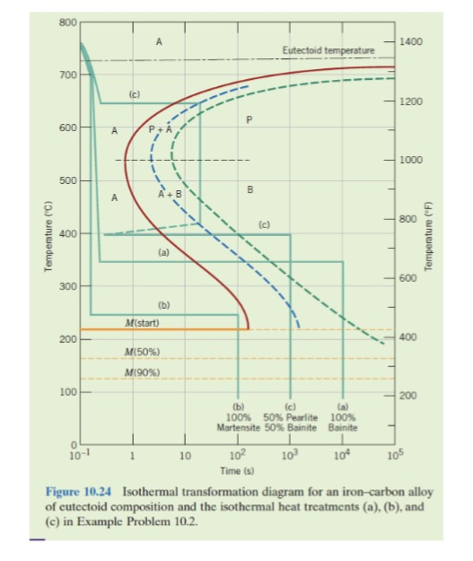
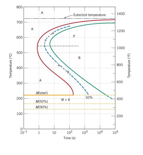
Isothermal transformation diagram for an iron–carbon alloy
PDF Chapter 9 Phase Diagrams Problem Solutions Lever Rule Chapter 9 Phase Diagrams Fe Fe3C Isothermal transformation diagrams and non equilibrium Fe C structures ... Iron-carbon (Steel) Phase Diagram w/ Pro-Eutectoid Step ... alloying elements, and 3) the heat treatment of the alloy. 9.2 In order for a system to exist in a state of equilibrium the free energy Effect of Multidirectional Isothermal Forging on ... The as-received material used in the study was a commercially produced TC4 alloy. The chemical composition of the alloy is shown in Table 1. The transition temperature of β-phase in this alloy was reported to be ~975 °C [ 20 ]. Table 1. Chemical composition of as-cast Ti-6Al-4V alloy (wt.%). Prediction of Hardenability Curves for Non-Boron Steels ... High-entropy alloys (HEAs) have attracted a wide range of academic interest for their promising properties as structural materials, among which the equiatomic FeCrNiCoMn HEAs have
Isothermal transformation diagram for an iron–carbon alloy. (PDF) Titanium microalloying of steel: A review of its ... PDF | Carbon neutrality of the steel industry requires the development of high-strength steel. The mechanical properties of low-alloy steel can be... | Find, read and cite all the research you ... Metals | Free Full-Text | Effect of Quenching Parameters ... Commonly these temperatures can be calculated using time-temperature-transformation (TTT) diagrams or through analytical expressions. ... The isothermal kinetic equation ... R.E. A general equation prescribing the extent of the austenite-martensite transformation in pure iron-carbon alloys and plain carbon steels. Acta Metall. 1959, 7, 59 ... Materials | Free Full-Text | Prediction of Hardenability ... Kirkaldy et al. believed that the inflection point of the phase transformation reaction rate is the same as that in TTT diagram and in proportion with the CCT diagram. Therefore, the points corresponding to the CCT diagram must correspond to the inflection point of the Jominy curve. Mechanical and Thermal Properties of Cu-25wt.%Fe-25wt.%Nb ... Wang et al. (Ref 14, 16) determined the phase diagram of the Cu-Fe-Nb system under thermodynamic equilibrium conditions and calculated its 1200 °C isothermal section. The phases that occur for the Fe-Nb system are presented in Fig. 2, generated by the thermodynamic database of the FactSage TM software.
Roles of Mn content and nanovoid defects in the plastic ... When the tensile strain reaches ε = 0.09, the fcc → hcp phase transformation takes place, as shown in Fig. 2 (j). In the subsequent deformation process, according to Fig. 2 (k), hcp martensite with a twin substructure begins to proliferate, and at the same time, a small amount of bcc martensite nucleates and grows. Material science and engineering 9th edition pdf ... transform the material to tempered martensite. Hence, the final microstructure is 100% tempered martensite. Hence, the final microstructure is 100% tempered martensite. 10.22 Make a copy of the isothermal transformation diagram for a 0.45 wt% C iron-carbon alloy (Figure 10.39), Free Materials Science And Engineering Callister 9th Hydrogen trapping and electrochemical corrosion behavior ... During reheating and isothermal stages, Cr, Cu and Mo are completely dissolved in the steels, and low diffusion coefficient during the subsequent rolling and cooling results in uniform distribution in the final microstructure. Small amounts of Cr, Cu, and Mo can improve the corrosion resistance of pipeline steels. Fig. 4 Metals | Free Full-Text | Phase Equilibria of CaO-SiO2 ... The 1200 °C isothermal phase diagram of CaO-SiO 2-La 2 O 3-Nb 2 O 5 system in reducing atmosphere was constructed and presented by spatial phase diagram, in which six equilibrium phase regions were divided. The research results can supplement the thermodynamic data of relevant silicate slag systems as well as guide the development of the ...
In situ thermal annealing transmission electron microscopy ... In situ thermal-annealing transmission electron microscopy (TEM) is a powerful characterization method to track the dynamics of microstructural changes, such as phase transformations or diffusion of atoms. 1-4 1. C. Hayzelden, J. L. Batstone, and R. C. Cammarata, " In situ transmission electron microscopy studies of silicide-mediated crystallization of amorphous silicon," Appl. Phys ... Prediction of Hardenability Curves for Non-Boron Steels ... High-entropy alloys (HEAs) have attracted a wide range of academic interest for their promising properties as structural materials, among which the equiatomic FeCrNiCoMn HEAs have Effect of Multidirectional Isothermal Forging on ... The as-received material used in the study was a commercially produced TC4 alloy. The chemical composition of the alloy is shown in Table 1. The transition temperature of β-phase in this alloy was reported to be ~975 °C [ 20 ]. Table 1. Chemical composition of as-cast Ti-6Al-4V alloy (wt.%). PDF Chapter 9 Phase Diagrams Problem Solutions Lever Rule Chapter 9 Phase Diagrams Fe Fe3C Isothermal transformation diagrams and non equilibrium Fe C structures ... Iron-carbon (Steel) Phase Diagram w/ Pro-Eutectoid Step ... alloying elements, and 3) the heat treatment of the alloy. 9.2 In order for a system to exist in a state of equilibrium the free energy
7 Make a copy of the isothermal transformation | Chegg.com
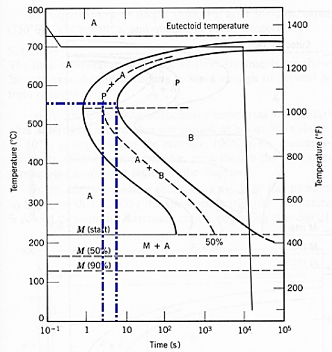
Solved: Using The Isothermal Transformation Diagram For An... | Chegg.com
Iron Carbon Phase Diagram

Isothermal Phase Transformation of U-Zr-Nb Alloys for Advanced Nuclear Fuels | IntechOpen
PPT - Chapter 11 Phase Transformations PowerPoint Presentation, free download - ID:6600469
Solved: 7.3. Using The Isothermal Transformation Diagram F... | Chegg.com
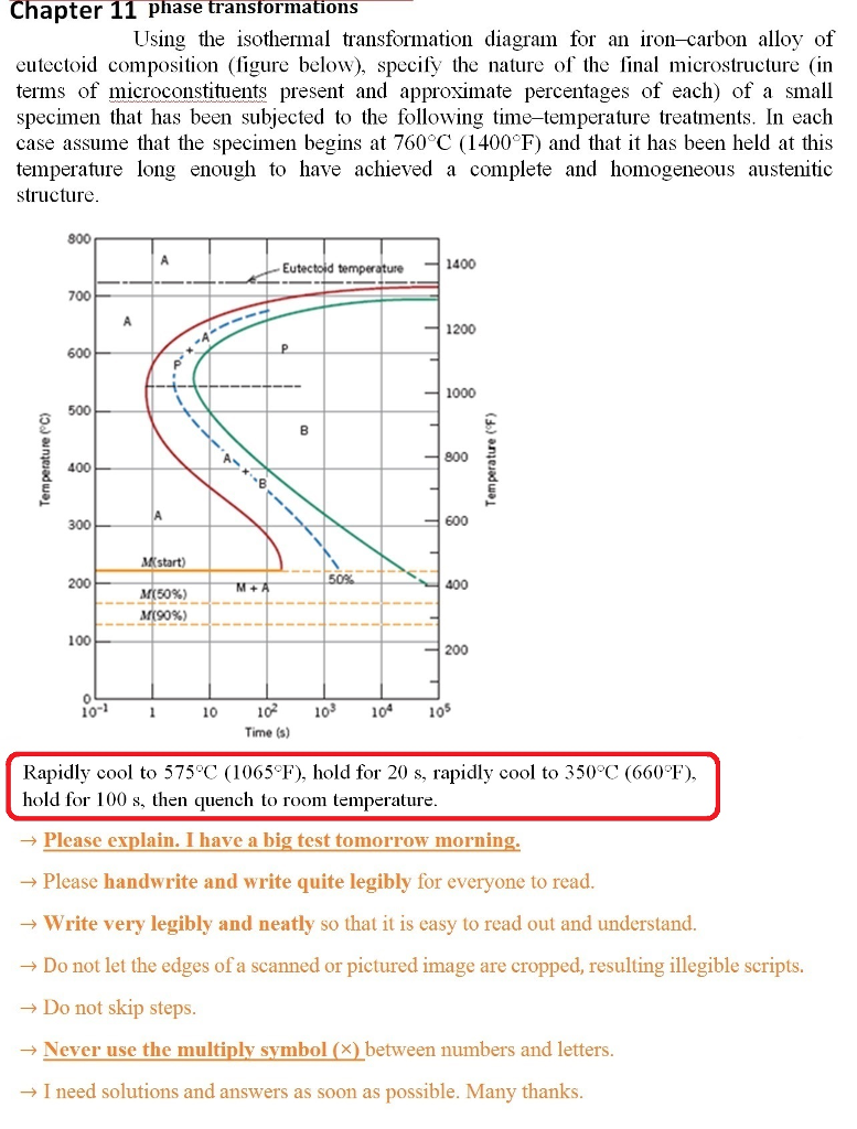
Solved: Using The Isothermal Transformation Diagram For An... | Chegg.com
Solved: Suppose that a steel of eutectoid composition is cooled... | Chegg.com
0 Response to "42 isothermal transformation diagram for an iron–carbon alloy"
Post a Comment