40 ni cu phase diagram
Example: Cu-Ni phase diagram (only for slow cooling conditions) Liquidus line: the line connecting Ts at which liquid starts to solidify under equilibrium conditions Solidus: the temperature at which the last of the liquid phase solidifies Between liquidus and solidus: P =2. Chapter 8 9 We have examined isomorphous phase diagrams, and used the example of the Cu-Ni phase diagram. In this module we will examine eutectic phase diagrams. A eutectic system has two components, and they have limited solubility. Upon cooling, the liquid will transform into two mixed solid phases. We will use the Pb-Sn phase diagram as an example.
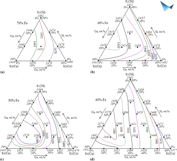
TYPE OF TERNARY DIAGRAM OBTAINED FROM THE BINARY DATA GIRT of the f.c.c. phase, at 1200abs., ,is a function of concentration in the ternary diagram forms a surface which is convex from below near the Cu-Ni and Ni-Cr sides, but shows a plait near the Cu-Cr side (compare Fig. 5, and also r. 20, Fig. 2).
Ni cu phase diagram
Phase Diagrams • Indicate phases as a function of T, C, and P. • For this course:-binary systems: just 2 components.-independent variables: T and C (P = 1 atm is almost always used). Phase Diagram for Cu-Ni system Fig. 11.3(a), Callister & Rethwisch 9e. (Adapted from Phase Diagrams of Binary Nickel Alloys, P. Nash, Editor, 1991. Reprinted The Cu-Ni phase diagram (Figure 9.3a) is shown below; the point labeled "G" represents the 63.8 wt% Ni-36.2 wt% Cu composition at 1250°C. As may be noted, point G lies within the α phase field. Therefore, only the α phase is present; its composition is 63.8 wt% Ni-36.2 wt% Cu. Phase Diagram. このサイトを検索 ... Ni-Cu. Data from RICT-Sol alloy database ver.1.0. Sign in | Recent Site Activity | Report Abuse | Print Page | Powered By Google Sites ...
Ni cu phase diagram. The binary phase diagram shown for the copper-nickel alloy indicates that these materials can form both liquid and solid solutions over the full range of composition from Cu to Ni. Above 1728 K, the melting point of pure Ni the alloys ar in the liquid phase. Between 1728 K and 1357 K (the melting point of Cu) the alloys can be either solid or ... Shown below is the Cu-Ni phase diagram (Figure 9.3a) and a vertical line constructed at a composition of 70 wt% Ni-30 wt% Cu. (a) Upon heating from 1300°C, the first liquid phase forms at the temperature at which this vertical line intersects the α-(α + L) phase boundary--i.e., about 1345°C. )-)- 0. Phase Diagram 1. Overview 2. Heating & Pouring 3. Solidification and Cooling 2 0. Alloys and Phase Diagram • Pure Metals • Alloys - Solid solutions • Substitutional Solid Solution (Zn/Cn and Cu/Ni) - Atomic radii is similar - Lattice type is the same • Interstitial Solid Solution - Smaller atoms are interstitially located ... Move the mouse over the phase diagram to view temperature and composition at any point. View micrographs for the Cu-Ni system. List all systems with phase diagrams
Phase Diagrams • Indicate phases as function of T, Co, and P. • For this course:-binary systems: just 2 components.-independent variables: T and Co (P = 1 atm is almost always used). • Phase Diagram for Cu-Ni system Adapted from Fig. 9.3(a), Callister 7e. (Fig. 9.3(a) is adapted from Phase Diagrams of Binary Nickel Alloys , P. Nash The Sn-Cu-Ni has become increasingly significant as it is used in several solder alloys and more generally both Cu and Ni are common substrates that interact with Sn-based solders in microelectronic applications. However, there is currently an insufficient understanding of the phase equilibria and the associated phase diagrams of many Sn alloys. Phase Diagrams • Indicate phases as function of T, Co, and P. • For this course: -binary systems: just 2 components. -independent variables: T and Co (P = 1 atm is almost always used). • Phase Diagram for Cu-Ni system Adapted from Fig. 9.3(a), Callister 7e. (Fig. 9.3(a) is adapted from Phase Diagrams of Binary Nickel Alloys, P. Nash 7.3. Al-Cu-Ni PHASE DIAGRAM This phase diagram is helpful in the analysis of 2618-type heat-resistant alloys and 339.0-type piston alloys that contain nickel, copper, and other alloying components (Tables 7.1 and 7.2). The ternary Al7Cu4Ni phase forms in the aluminum corner of the Al-Cu-Ni system.
The Al 7 Cu 4 Ni 1 phase (i.e. τ), with a small homogeneity range, is the only ternary phase in the Al-Cu-Ni system [10,35,36]. The Al 7 Cu 4 Ni 1 phase has a CsCl-type base structure, where along the c axis 8 Al atoms alternates with 6 heavy atoms (i.e. Cu and Ni) and 2 vacant sites . pressure to be constant at one atmosphere. Phase diagrams for materials with more than two components are complex and difficult to represent. An example of a phase diagram for a ternary alloy is shown for a fixed T and P below. Phase diagrams for binary systems ternary phase diagram of Ni-Cr-Fe The Ni-Cu alloy phase diagram. The initial condition of the ... The Cu-Ni phase diagram from [1991Cha, 1994Cha] Figure 1 from evaluation report: Cu-Ni Binary Phase Diagram Evaluation. Cite this page. Citation Phase diagram available to subscribers; If you are having trouble in accessing SpringerMaterials remotely during the COVID-19 pandemic,
Part of the phase diagram of the Cu-Ni-Mn system from 0 to 20% Ni and from 30 to 50% Mn is refined with the help of a theoretical analysis and based on the experimental data.
6. Use the Copper-Nickel phase diagram below to describe how coring/segregation develops in a Copper-Nickel alloy. For your discussion, consider an alloy that is 80 wt%Ni- 20 wt% Cu. Composition fat% NO 20 40 60 80 100 1600 2800 1500 Liquid 1453"c 2600 1400 Liquidus line Solidus line 2400 Temperature (°C) 1300 Temperature (°F) B 1200 2200 ...
Binary phase diagram If a system consists of two components, equilibrium of phases exist is depicted by binary phase diagram. For most systems, pressure is constant, thus independently variable parameters are -temperature and composition. Two components can be either two metals (Cu and Ni), or a metal and a compound (Fe and Fe3C), or two ...
There is two types of important phase diagrams are used one is a slow process diagram, and another is a fast process diagram. Answer and Explanation: 1 Phase diagram of the Ni-Cu is
Mechanical Engineering questions and answers. Use the phase diagrams for Cu-Ni and Cu-Ag systems below to answer questions for 10B.1. Note that these correspond to Figure 10.3 (a) and Figure 10.7, respectively in the textbook. Composition (at% Ni) 20 0 1600 40 60 80 100 1 1 2800 1500 Liquid 1453°C Composition (at Ag) 40 T 1 T T 20 2600 0 1200 ...
The density of copper (8.93 kg/dm 3 at 20 °C) varies only slightly with increasing nickel content (density of nickel at 20 °C = 8.9 kg/dm 3) and is 8.9 kg/dm3 for all Cu-Ni alloys specified in DIN 17 664. This aspect can also be seen in Table 7 with the physical properties of the Cu-Ni resistance alloys to DIN 17 471.
by J Sopousek · 2014 · Cited by 80 — 2. Thermodynamic calculation of the Cu–Ni nanoalloy phase diagram ... Nanoparticles have an increasing surface to volume ratio with decreasing particle size and ...
This video explains binary phase diagrams, specifically the Cu-Ni System. For further studies: visit https://www.doitpoms.ac.uk/tlplib/phase-diagrams/printal...
A good interpretation of a binary phase diagram that is easy to understand and interpret is the Cu-Ni system. This diagram has three different phase regions ...
#modimechanicalengineeringtutorials, #mechanicalmagicmechanicallearningtutorials,Welcome to My YouTube Channel MODI MECHANICAL ENGINEERING TUTORIALS.This ch...
The calculated phase diagram of Cu-N system has been validated. At T > 630 K, in the N-rich corner, large scatter in data has been observed and discussed in detail. The other binary systems, Cu-S and Ni-S, have been also critically reviewed together with the ternary Cu-N-S system.
The Cu-Ni and binary phase diagram (Figure 10.3) is the simplest type of binary phase diagrams for two metals. Figure 10.3 shows that Cu and Ni are mutually soluble at room temperature throughout the entire range of compositions. Remember from Chapter 5that we discussed the HumeRothery - rules for deciding when two metals will be soluble, and we concluded that Cu and Ni form a perfect solid ...
Cu-Ni phase diagram A(1100, 60): 1 phase: B(1250, 35): 2 phases: L + Determination of phase(s) present Melting points: Cu = 1085°C, Ni = 1453 °C Solidus - Temperature where alloy is completely solid. Above this line, liquefaction begins. Liquidus - Temperature where alloy is completely liquid. Below this line, solidification begins. 17 • Rule 2: If we know T and Co, then we know:--the ...
Phase Diagram. このサイトを検索 ... Ni-Cu. Data from RICT-Sol alloy database ver.1.0. Sign in | Recent Site Activity | Report Abuse | Print Page | Powered By Google Sites ...
The Cu-Ni phase diagram (Figure 9.3a) is shown below; the point labeled "G" represents the 63.8 wt% Ni-36.2 wt% Cu composition at 1250°C. As may be noted, point G lies within the α phase field. Therefore, only the α phase is present; its composition is 63.8 wt% Ni-36.2 wt% Cu.
Phase Diagrams • Indicate phases as a function of T, C, and P. • For this course:-binary systems: just 2 components.-independent variables: T and C (P = 1 atm is almost always used). Phase Diagram for Cu-Ni system Fig. 11.3(a), Callister & Rethwisch 9e. (Adapted from Phase Diagrams of Binary Nickel Alloys, P. Nash, Editor, 1991. Reprinted


0 Response to "40 ni cu phase diagram"
Post a Comment