40 draw the shear diagram for the shaft.
3. Draw the Shear, Normal, and Bending Moment Diagrams 4. Identify the critial locations, x along the structure where Vmax, Nmax, and Mmax exist. 5. Identify which stresses exist Normal Stress pure Shear Stress Transverse Shear Stress Normal Bending Stress Torsional Shear Stress pressure Vessel Stresses 6. Solved Draw The Shear Diagram For The Beam Chegg Com Then click on add segment button to add functions between the lines. Problem 778 part a draw the shear diagram for the beam. Correct problem 753 part a draw the shear diagram for the beam. Draw the shear and moment diagrams for the shaft. Your shear diagram is correct.
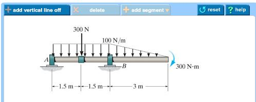
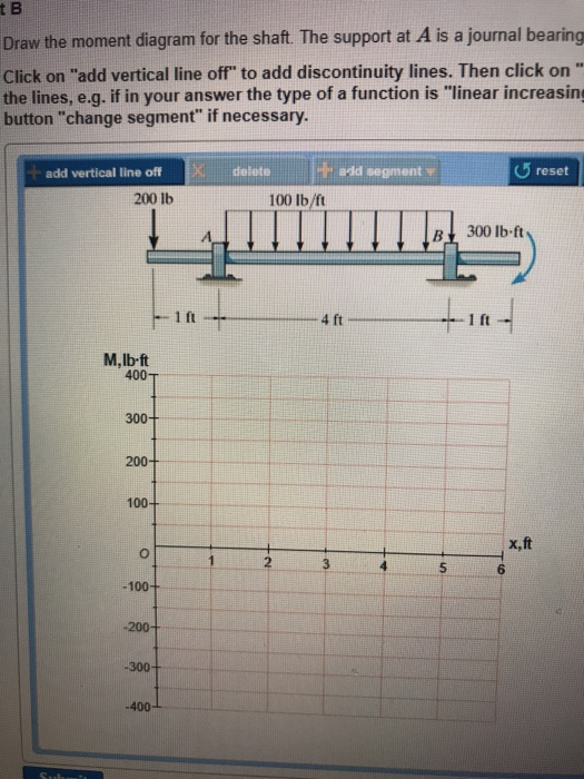
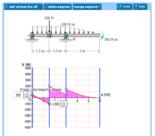
A) Draw the shear diagram for the shaft. 300 N 100 N/m 300 N·m 1,5 m+1. B) Draw the moment diagram for the shaft. Show transcribed image text ... a) Calculate the shear for ce and bending moment for the beam subjected to a concentrated load as shown in the figure. The n, draw the n, draw the
Draw the shear diagram for the shaft.
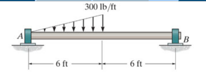
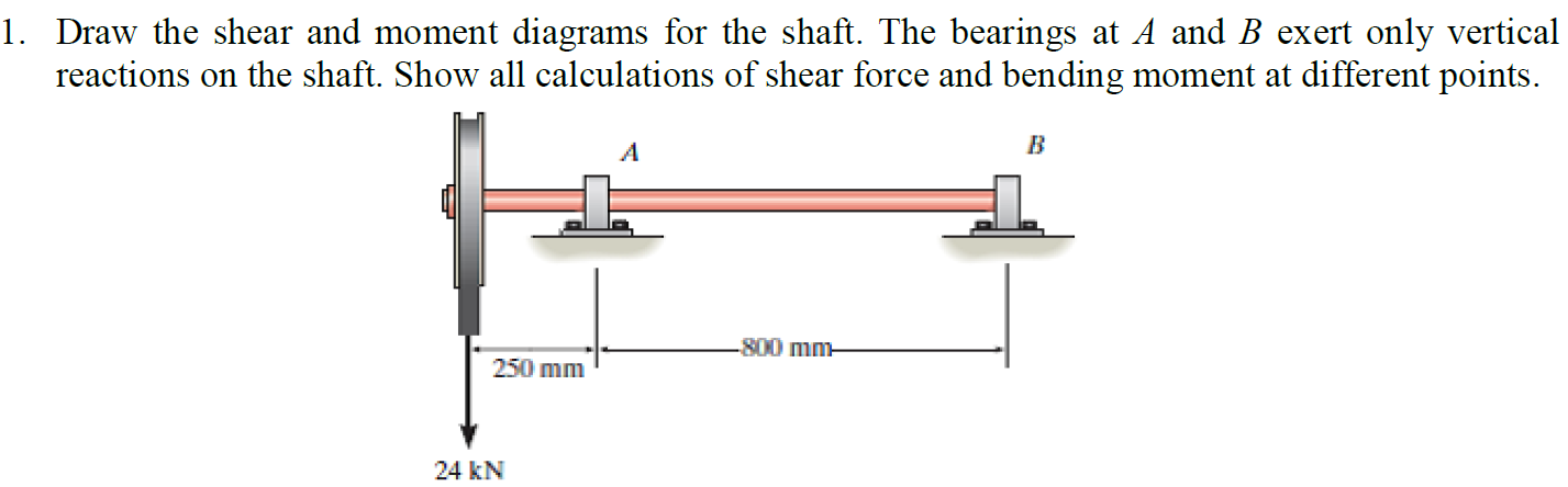
a) Calculate the shear force and bending moment for the beam subjected to a concentrated load as shown in the figure. Then, draw the shear force diagram (SFD) and bending moment diagram (BMD). b) If P = 20 kN and L = 6 m, draw the SFD and BMD for the beam. P kN L/2 L/2 A B EXAMPLE 4 How the bending moment diagram of an overhanging beam will be if only we can draw the shear force diagram since it dictates the shape of bending moment . 6-5. Draw the shear and moment diagrams for the beam. 2 m. 3 m. 10 kN. 8 kN. 15 kNm. 6-6. Draw the shear and moment diagrams for the overhang beam. A. 6-5. Solution for 11-1. Draw the shear and moment diagrams for the shaft. The bearings at A and Bexert only vertical reactions an the shaft. -N0 mm- 250 mim 24 kN
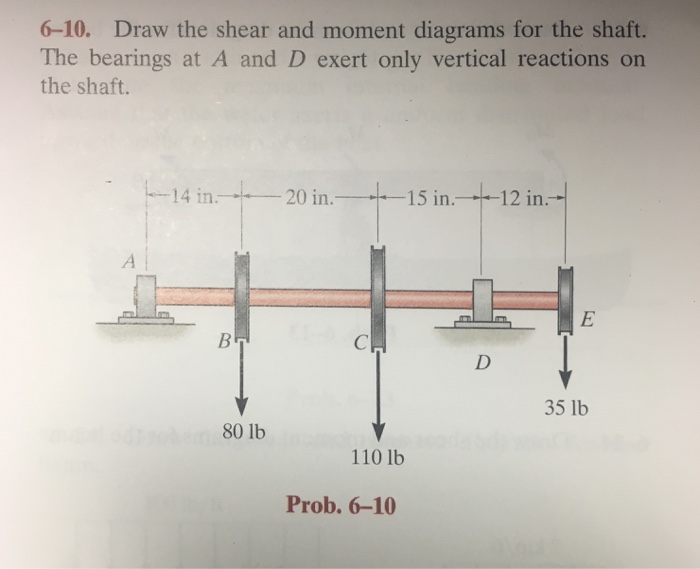
Draw the shear diagram for the shaft.. Draw the shear and moment diagrams for the shaft. The bearings at A and D exert only vertical reaction on the shaft.The loading is applied to the pulleys at B and C and E. A B 14 in. 20 in. 15 in. 12 in. 80 lb 110 lb 35 lb C D E Ans: M (lb in) x x V (lb) 50 82.2 2.24 1151 1196 108 420 35 Hibbeler_Chapter 6_Part 1 (463-486).qxd 2/12/13 11:06 AM ... To create the moment diagram for a shaft, we will use the following process. Solve for all external forces and moments, create a free body diagram, and create the shear diagram. Lined up below the shear diagram, draw a set of axes. Question: Draw the shear and moment diagrams for the shaft (a) in terms of the parameters shown; (b) set P = 9 kN, a = 2 m, L = 6 m. There is a thrust bearin... The torque diagram of a shaft is analogues to the shear force and bending moment diagram of a beam. It is an important engineering diagram from the pulley shaft design point of view. The steps required to draw it will be discussed with the help of the following example:
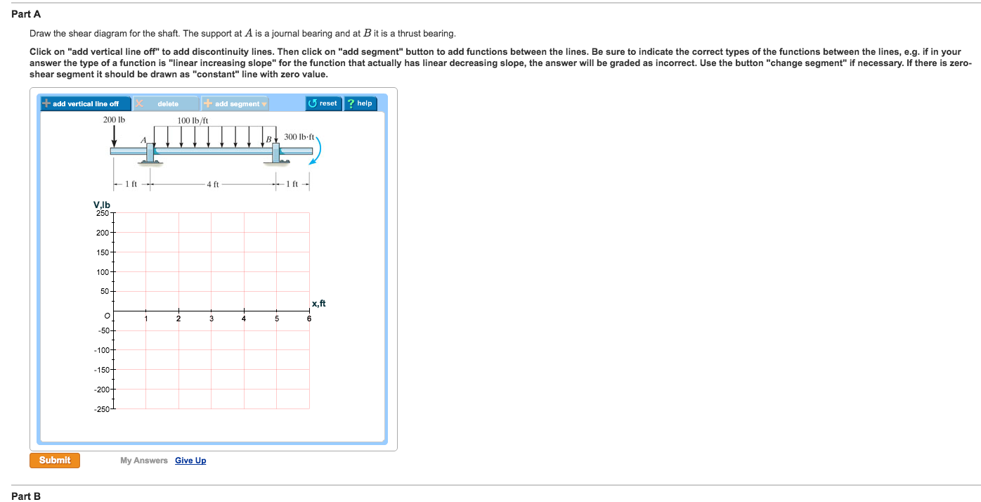
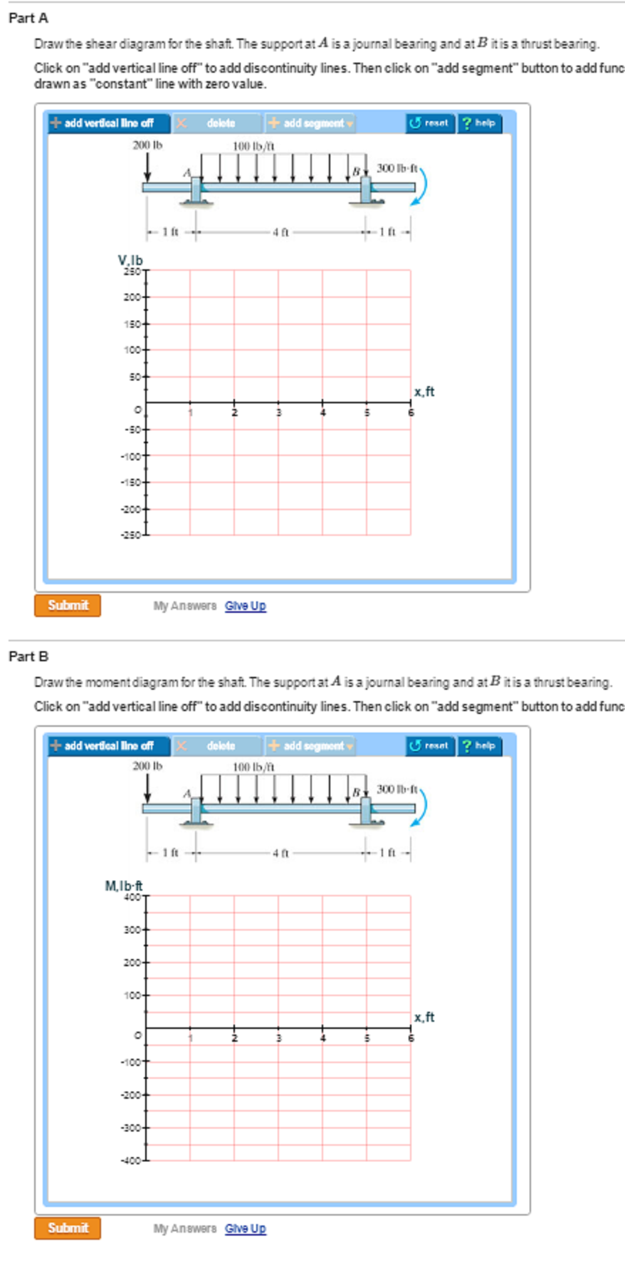
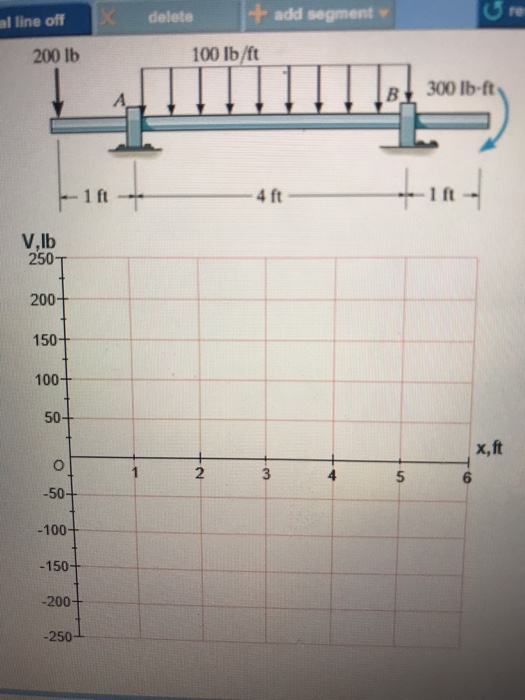
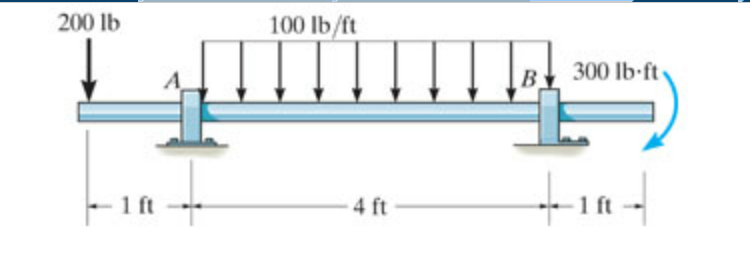
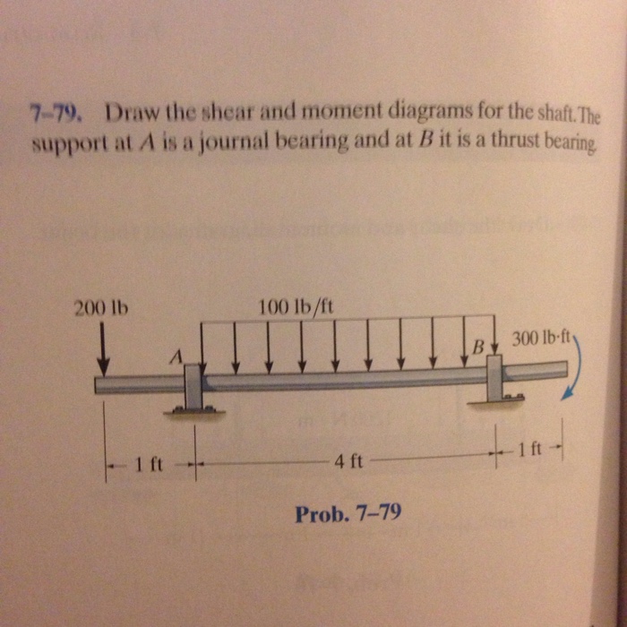
Shear diagrams always begin and end at zero, with all of the forces on the member shown in between.Starting from the left, the first force you come across is the 10 lb downward force at the left end. This is the first point of data, draw a line from zero to negative 10.. Continuing on the next force is 21.67 lb upward at the A support. Answer to Draw the shear diagram for the shaft. The support at A is a journal bearing and at B it is a thrust 200 1b 100 lb/ft B 300 lb.ft bearing. 1 ft 4.1 answer · Top answer: Explanation is shown below. Image transcriptions Free Body Diagram : 20 016 100 lb /ft 300 16- f+ A B RA RB Ift 4 ft Ift Reactions : EMAT + = 0i Rex 4 ... Jan 28, 2021 — 1 Answer to Draw the shear and moment diagrams for the shaft. The support at A is a journal bearing and at B it is a thrust bearing.1 answer · Top answer: Page 200 lb • | 100 lbise zoolb-fie d I 2 ? ? A I ft aft Zoolb B R Ball aft agt ago tay tay • f 600 Take moment (A) 11 400x2 + 300 goo foy (+) +200x1 ... A) Draw the shear diagram for the shaft. The support at A is a journal bearing and at B it is a thrust bearing. B) Draw the moment diagram for the shaft. The support at A is a journal bearing and at B it is a thrust bearing.
Free online beam calculator for generating the reactions, calculating the deflection of a steel or wood beam, drawing the shear and moment diagrams for the beam. This is the free version of our full SkyCiv Beam Software. This can be accessed under any of our Paid Accounts, which also includes a full structural analysis software. Draw shear-force and bending-moment diagrams for the shaft. If needed. make one set for the horizontal plane and another set for the Vertical plane. At the point of maxtmum bending moment, determine the bending stress and the torsional shear stress. At the point of maximum bending moment. determine the principal stresses and the maximum shear ... Draw the shear and moment diagrams for the shaft : 2018051. 11-135. Draw the shear and moment diagrams for the shaft if it is subjected to the vertical loadings of the belt, gear, and flywheel. The bearings at A and B exert only vertical reactions on the shaft. 2-12 Finally, we end this section with a discussion of torque diagrams. These are usually simpler than shear and bending moment diagrams, and can be illustrated with the following example. Example Draw the torque diagram for the cantilever shaft shown. Determine the maximum torque in the shaft. 5 kNm 7 kNm 12 kNm 1 m 1 m 1 m fixed end 13. 2-13
Solved: Draw The Shear And Moment Diagrams For The Shaft ...
Shear and Moment Diagrams.The shear and moment diagrams shown in Fig. 6-6c are obtained by plotting Eqs. 1 and 2.The point of zero shearcan be found from Eq. 1: From the moment diagram, this value of x happens to represent the point on the beam where the maximum momentoccurs, since by Eq. 6-2, the slope From Eq. 2, we have = wL2 8 M max = w ...

Image from page 341 of "Mechanics of engineering. Comprising statics and dynamics of solids: and the mechanics of the materials of constructions, or strength and elasticity of beams, columns, arches, shafts, etc" (1888)
Draw the shear and moment diagrams for the shaft in terms of the parameters shown; There is a thrust bearing at A and a journal bearing at B. Units Used: kN = { 10 }^{ 3 } N. Given: P = 9 kN. a = 2 m . L = 6 m
Ch06 07 pure bending & transverse shear
362 CH\"'PfE~ 7 INTE~N\"'l FO~ CES7_71. Draw the shear and moment diagra ms for the lathe 7_74. Draw the shear and moment diagrams for the beam.shaft if il iS5ubjected to the loadssho\"·n.The bearing al;\ isa journal bearing, and 8 is a thrust bearing.
SHEAR FORCE AND BENDING MOMENT DIAGRAM FOR SIMPLY SUPPORTED BEAM WITH POINT LOAD AT MIDPOINT - Mechanical engineering concepts and principles
Draw the torque diagram for each shaft. PROBLEM 5-3 The solid shaft is fixed to the support at C and subjected to the torsional loadings shown. Determine the shear stress at points A and B and sketch the shear stress on the volume elements located at these points.
SOLVED:Draw the shear and moment diagrams for the shaft if it is subjected to the vertical loadings of the belt, gear, and flywheel. The bearings at A and B exert only vertical
Draw the shear and moment diagram for the shaft. The bearing at A and B exert only vertical reactions on the shaft. Also, express the shear and moment in the shaft as a function of {eq}x {/eq ...
Solved: The Shaft Is Supported By A Smooth Thrust Bearing ...
Draw the shear and moment diagrams for the shaft. The bearings at A and B exert only vertical reactions on the shaft. © 2010 Pearson Education, Inc., Upper ...11 pages

Draw the shear and moment diagrams for the shaft. The ...
.7—65. The shaft is supported by a smooth thrust bearing at A and a smooth journal bearing at B. Draw the shear and moment diagrams for the shaft. 4001b 6001b 3001b 600 1b 4001b 3001b zft v(lb) (lbåt) 275 -325 2ft 6251b 1350 1250 Momenf
The shaft is supported by a smooth thrust bearing at A and smooth journal bearing at B. Draw the shear and moment diagrams for the shaft. | Study.com
In This video, you can learn how to develop sfd and bmd graphically without doing any equation. this is useful in structural analysis. _____...
Solved: Part A Draw The Shear Diagram For The Shaft. The S ...
(Solution Download) Draw the shear and moment diagrams for the shaft in. Draw the shear and moment diagrams for the shaft in terms of the parameters shown; there is a thrust bearing at A and a journal bearing at B. Units Used: kN = 103 N Given: P = 9kN a = 2 m L = 6 m
Solved: T A Draw The Shear Diagram For The Shaft. The Supp ...
Jan 12, 2021 — The bearings at A and B exert only vertical reactions on the vertical shaft. – Bending, Mechanics of Materials, by R C Hibbeler. ( ...
Solved: Strength Of Materials Please Write Symbols And Num ...
Draw the shear and moment diagrams. Step-by-Step ...
Solved: Estion 4 25 Points Save Draw The Shear And Moment ...
4.0 Building Shear and Moment Diagrams. In the last section we worked out how to evaluate the internal shear force and bending moment at a discrete location using imaginary cuts. But to draw a shear force and bending moment diagram, we need to know how these values change across the structure.
Chapter 7
Shear and moment diagrams and formulas are excerpted from the Western Woods Use Book, 4th edition, and are provided herein as a courtesy of Western Wood Products Association. Introduction Notations Relative to "Shear and Moment Diagrams" E = modulus of elasticity, psi I = moment of inertia, in.4 L = span length of the bending member, ft.
Solved: Draw The Shear Diagram For The Shaft. The Support ...
The shaft is supported by a smooth thrust bearing at A and a smooth journal bearing at B. Thank you!!! Expert Answer.

Solved: Given: A Shaft Subjected To The Shown Concentrated ...
Draw the shear and moment diagrams for the beam, and determine the shear and moment throughout the beam as functions of x. 2 kip/ft 8 kip x 10 kip 40 kip ft A 30 kip ft B 5 ft 5 ft 2 kip/ft 5 ft 6-19. Draw the shear and moment diagrams for the beam. 06 Solutions 46060_Part1 5/27/10 3:51 PM Page 338
Draw the shear force and the bending moment diagrams of the shaft ABCD for xy- and xz- planes. Plot torque diagram. | Course Hero
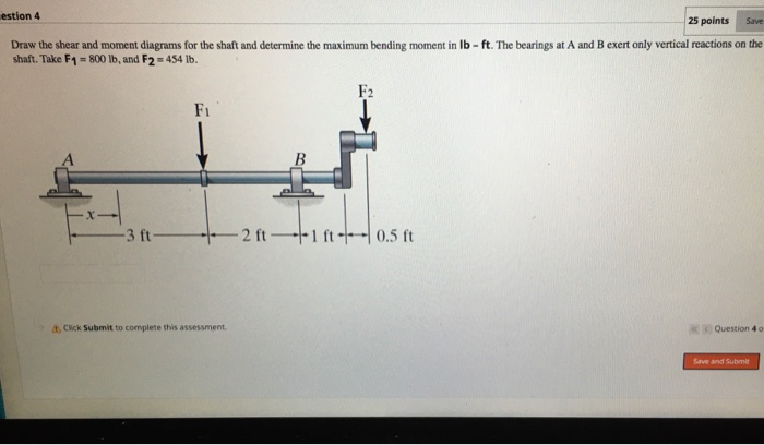
Draw the shear and moment diagrams for the shaft and determine the shear and moment throughout the shaft as a function of x. The bearings at A and B exert only vertical reactions on the shaft. x BA 800 lb 500 lb 3 ft 2 ft 0.5 ft 0.5 ft 06 Solutions 46060_Part1 5/27/10 3:51 PM Page 336

Draw The Shear Diagram For The Compound Beam Which Is Pin ...
1 answerThe figure below represents the free body diagram of the shaft. Free Body Diagram. Take the moment about A,. {eq}\begin{align*} \sum {{M_A}} ...
Solved: Draw The Shear And Moment Diagrams For The Shaft ...
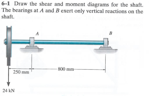
Draw the shear and moment diagrams for the beam. 2 kip 2 kip 2 kip 2 kip Kip) M(Kp-ft) 6—1. Draw the shear and moment diagrams for the shaft.The hearings at A and B exert only vertical reactions on the shaft. V(XN) 800 mm 250 mm 75 24 kN . 6-10. The engine crane is used to support the engine,

Image from page 130 of "1921 Griffith and Turner Co. : farm and garden supplies" (1921)
Solution for 11-1. Draw the shear and moment diagrams for the shaft. The bearings at A and Bexert only vertical reactions an the shaft. -N0 mm- 250 mim 24 kN

SHEAR STRESS DISTRIBUTION IN THE WEB OF I-SECTION ...
How the bending moment diagram of an overhanging beam will be if only we can draw the shear force diagram since it dictates the shape of bending moment . 6-5. Draw the shear and moment diagrams for the beam. 2 m. 3 m. 10 kN. 8 kN. 15 kNm. 6-6. Draw the shear and moment diagrams for the overhang beam. A. 6-5.

Draw The Free Body Diagram For The Following Diagr ...
a) Calculate the shear force and bending moment for the beam subjected to a concentrated load as shown in the figure. Then, draw the shear force diagram (SFD) and bending moment diagram (BMD). b) If P = 20 kN and L = 6 m, draw the SFD and BMD for the beam. P kN L/2 L/2 A B EXAMPLE 4
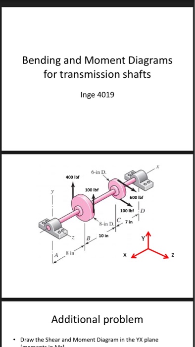
Solved: Bending And Moment Diagrams For Transmission Shaft ...

Shear Force and Bending Moment Diagrams | Download ...

Draw the shear and moment diagram for the shaft. The ...
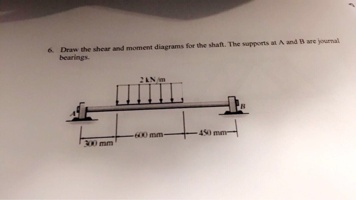
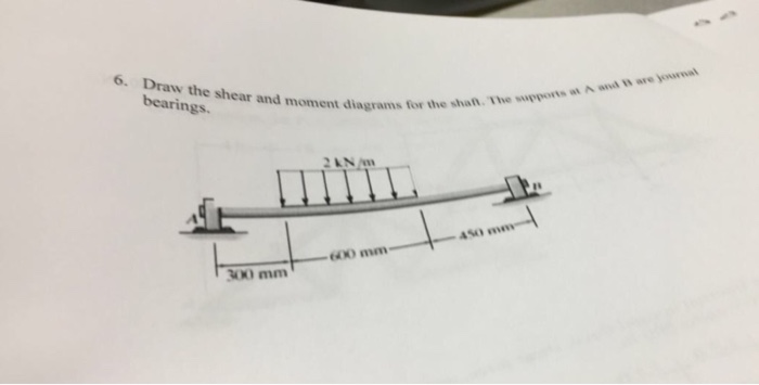
Solved 6-6. Draw the shear and moment diagrams for the shaft | Chegg.com
Solved: Draw The Shear And Moment Diagrams For The Shaft ...
Solved: Draw The Shear And Moment Diagrams For The Shaft ...
Answered: Draw the shear and moment diagrams for… | bartleby

37 draw the shear diagram for the shaft. - Wiring Diagram Info

Solved: Draw The Shear Diagram For The Shaft. The Bearing ...
Solved: T A Draw The Shear Diagram For The Shaft. The Supp ...
Solved: Part A Draw The Shear Diagram For The Shaft. The S ...

Problem 778 Part A Draw The Shear Diagram For The Beam ...
Solved: Draw The Shear And Moment Diagrams For The Shaft ...

Solved: Draw The Shear And Moment Diagrams For The Shaft A ...

Draw the shear and moment diagrams for the shaft and ...
Solved: The Shaft Is Supported By A Smooth Thrust Bearing ...
329 6–1. Draw the shear and moment diagrams for the shaft. The bearings at A and B exert only vertical reactions on the shaft.
Solved: Draw The Shear And Moment Diagrams For The Shaft ...
0 Response to "40 draw the shear diagram for the shaft."
Post a Comment