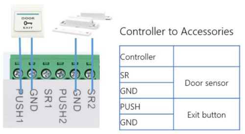
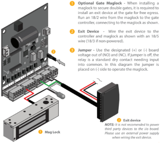
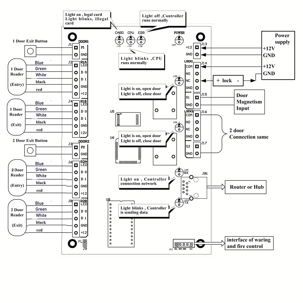
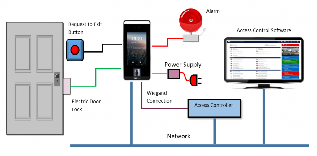
38 request to exit wiring diagram
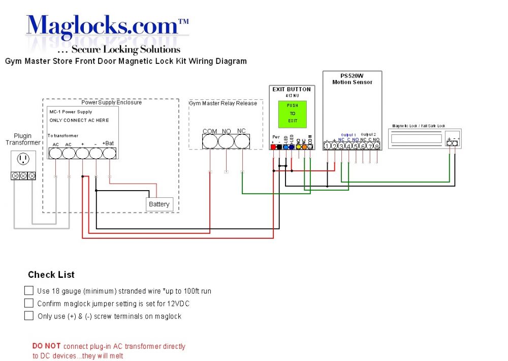
- WIRING INSTRUCTIONS— Magnetic lock or fail safe strike with button, keypad, maintained button and remote receiver. wired in series Power Supply for fail safe strikes and magnetic locks should be DC. If this is not available you may use an AC power source and wire inline a “Full Wave Bridge” rectifier. This will conver t the AC to DC.
LocksOnline Wiring Diagram 004. Oct 30, · Request to Exit Wiring Diagram ds ds installation guide high performance request to 3 3 8 disabling the request to exit the ds can be disabled by using terminal r and an external device such as an access control or burglar alarm system. Push Buttons.
How to connect a Request to Exit button in a Kisi stand-alone setup. When installing Kisi as a stand alone product on a Fail-Safe lock, it is important to understand how to wire necessary, non-Kisi components to the setup. This guide specifically will explain the wiring of a Request to Exit (REX) button.

Request to exit wiring diagram
Wiring Diagram: Installation: 1. Run four wires through the wall to a single-gang or slimline back-box. 2. Connect the four wires from the back-box to the Request-to-Exit Sensor according the Wiring Diagram above. 3. Screw the plate into the back-box, taking care not to crimp the wires. 4. Remove clear protective film from the sensor before use.
Search Wiring Diagrams for HES and Securitron products. Use the fields below to narrow down your search. You can also view all Wiring Diagrams by leaving the fields blank and clicking the "Search" button. PRO TIP: Be Broad! There are additional filters on the Results page to further narrow down your search.
DS150i/DS151i Installation Guide Request-to-Exit PIR Detectors 1.0 Description The DS150i is a passive-infrared detector designed for request to exit (REX) applications. It is UL Listed as an access control device under the UL 294 standard and is listed for Class I for UL Canada (ULC-S319). For
Request to exit wiring diagram.
ENFORCER Outdoor Piezoelectric Request to Exit Pushbutton -LARM U.S.A., Inc 3SECO Wiring the Manual Override: SD-6176-SSVQ and SD-6276-SSVQ Only Connect the manual override button with the included wires. Notes a. Remove the thin panel on the bottom of the plastic cover to allow wiring to pass through. b.
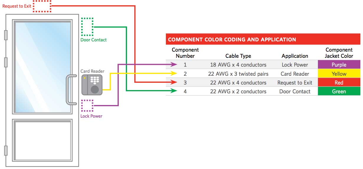
A crucial step in setting up your push-to-exit button is properly wiring all the components. In an IP system like Kisi, this will involve the door lock, the access reader, the controller, the power supply, and the push-to-exit button (as well as optional contact sensors). The following diagram outlines the setup with an electric strike lock.
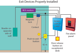
BEA has a complete line of request-to-exit (REX) products including sensors, locking devices, push buttons and keypads. Building codes often require two forms of exit devices on a door, such as a motion sensor and a push button, to ensure that occupants are safely able to exit a building. Our sensors help meet these codes.
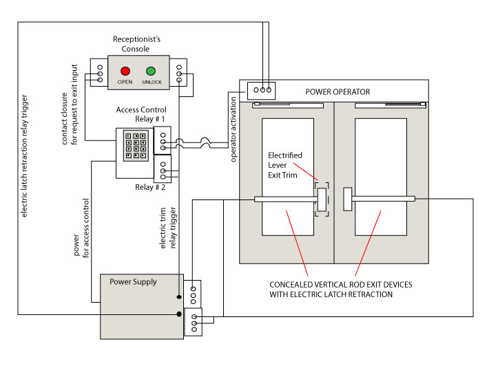
The following common wiring diagrams are available: One Single Door with Panic Bar. Electric Latch Retraction, with Auto Operator ... riser diagrams falcon exit devices ... wiring diagram request form . Common Wiring diagrams . wiring diagram for QEL panics ...

Visionis vis-7000 indoor green square request to exit button for door access control with led light, nc, c and no outputs












0 Response to "38 request to exit wiring diagram"
Post a Comment