37 emon dmon wiring diagram
MAINS Line Voltage & Current Sensor Wiring. Diagrams. 19. Section 4.6. Installation Overview. 20. Section 5.0. Monitoring Multiple Loads with One Meter.
® www.emon.com info@emon.com E-Mon D-Mon ... Wiring Diagrams Section 5.6 Line Voltage/Sensor Diagnostics 13 Section 5.7 RS-485 Communications 15
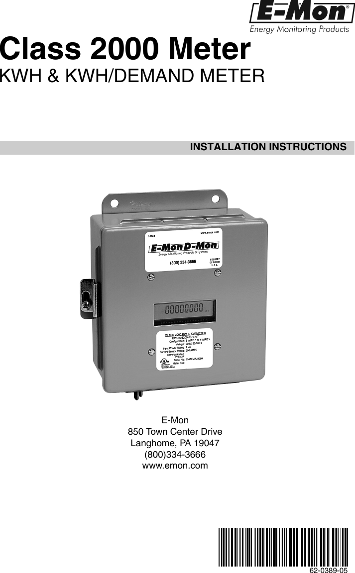
62-0396-03 INSTALLATION INSTRUCTIONS E-Mon Class 2000 Meter KWH & KWH/DEMAND METER 62-0396_C.fm Page 1 Wednesday, May 9, 2018 3:35 PM

Emon dmon wiring diagram
Class 2000 Meter KWH & KWH/DEMAND METER INSTALLATION INSTRUCTIONS E-Mon 850 Town Center Drive Langhome, PA 19047 (800)334-3666 www.emon.
INSTALLATION INSTRUCTIONS. Class 2000 Meter. KWH & KWH/DEMAND METER. E-Mon. 850 Town Center Drive. Langhome, PA 19047. (800)334-3666 www.emon.com ...
Class 1000 Installation Manual - E-Mon · METER1. · InformationThe · D- · ® · kWh meter is a 2-element meter used to monitorelectric power usage of individual loads ...
Emon dmon wiring diagram.
INSTALLATION DIAGRAM 1-PHASE, 2-WIRE 120 or 277 VOLT INSTALLATION DIAGRAM (Class 1000 Series Only) *** * These terminals are not used in Class 1000 installations. LINE VOLTAGE CURRENT SENSORS ∅A ∅B ∅C ∅ W B W B W B A ∅B ∅C N * LOAD SOURCE A B C
Dec 12, 2017 · Damon wiring diagram update added mod irv2 forums hints popupportal battery disconnect switch doesn t astoria motorhome manua ls 485pg motor and 50 similar items resolved electrical problem slide out will not retract slideouts fmca rv a community of rvers have 2003 p32 workhorse chasis auto brake failed low pressure by actuator blew 10 amp fuse in box… Read More »
Section 6.4 Current Sensor Installation & Wiring 17 Section 6.5 Main Power & Current Sensor Wiring Diagram 19 Section 6.6 Line Voltage/Current Sensor Diagnostics 20 Section 6.7 RS-485 Wiring 21 Section 6.8 RS-232 Communications 24 Section 6.9 Modem Wiring 26 Section 6.10 Modbus RTU Wiring 29 Section 6.11 BACnet MS/TP Wiring 30
Jan 17, 2019 · Emon Demon Wiring Diagram. This E-Mon DMon meter model must be installed indoors, in an area that is free NOTE: Refer to the Wiring Diagrams, for further information on current sensor. Main Power and Sensor Wiring Diagrams Section Line Voltage / Current Sensor Diagrams. 13 Device description: Emon Dmon Energy Meter. R.
Section 5.3 Current sensor installation and wiring 11 Section 5.4 Main power & sensor wiring diagrams 13 Section 5.5 Line voltage/current sensor diagnostics 14 Section 5.6 RS-485 wiring 15 Section 5.7 Modem wiring 16
Main Power & Sensor Wiring Diagrams. 11. Section 4.5. Line Voltage/Current Sensor Diagnostics 12. Section 5.0. Monitoring multiple loads with one meter.32 pages
www.emon.com info@emon.com. E-Mon D-Mon®. Installation Manual. Class 5000. Advanced KWh/Demand Meter. E-Mon, LLC - 850 Town Center Drive-Langhorne, PA 19047 ...28 pages









0 Response to "37 emon dmon wiring diagram"
Post a Comment