35 draw a top-down diagram of your setup from part e
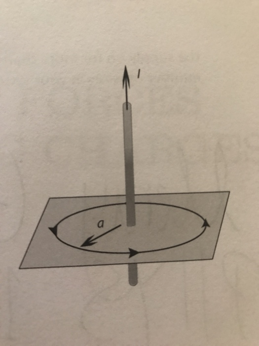
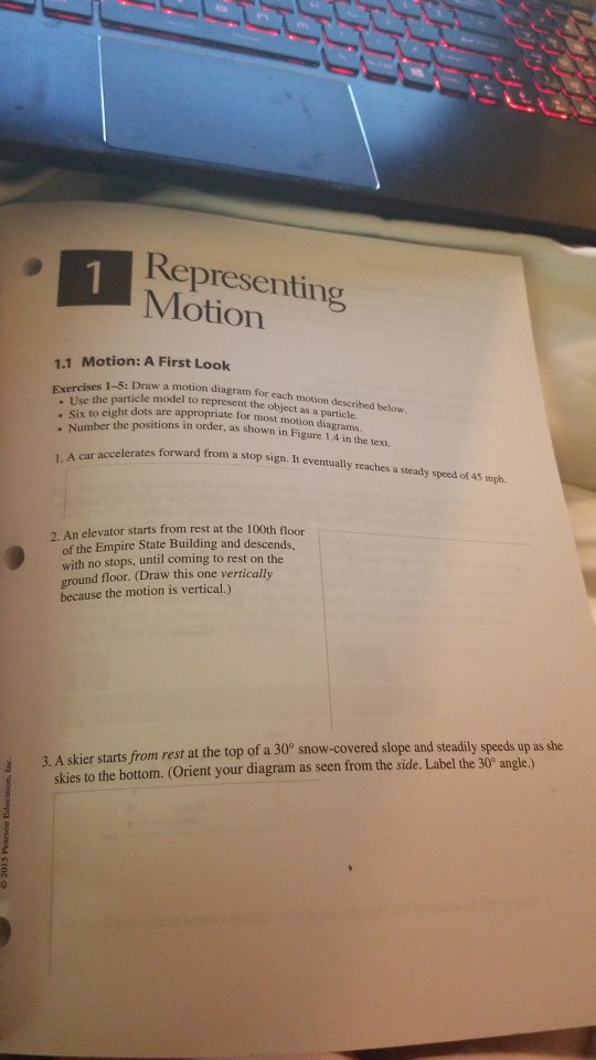
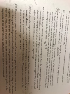
1. (3.5) Draw a top-down 2D diagram of your setup in part E (imagine looking from above). This diagram should include: a. The cardinal directions (N,S,E,W) b. The direction of current in the wires (8 for into, and O for out of the page) c. The direction of the compass needle (an arrow pointing to its north) d. You can use colors to classify similar entities or to highlight key areas in your diagrams. Drawing ER Diagrams Using Creately. ... Draw the ";E-R" for the supplier and parts database. can i get the ER diagram for this. 20.03.2014 - reply. ... on top of the ballon u can write the entity names. 07.11.2013 - reply.
wheat milling machines label diagrams simple vertical milling machine diagram Simple Vertical Milling Machine a label diagram of a grinding machine ...
Draw a top-down diagram of your setup from part e
Figure 5.32 (a) The free-body diagram for isolated object A. (b) The free-body diagram for isolated object B. Comparing the two drawings, we see that friction acts in the opposite direction in the two figures. Because object A experiences a force that tends to pull it to the right, friction must act to the left. Because object B experiences a component of its weight that pulls it to the left ... ... metallurgyThe working principle of cone crushers is explained to understand what application to best use the fine cone crusher in, diagrams of how a ... We use cookies and comparable technologies to provide certain functions, to improve the user experience and to offer interest-oriented content.
Draw a top-down diagram of your setup from part e. out of danger during let-down. Never draw a bow with a peak weight above your comfort level. Always use a wrist sling when drawing a bow. d. Never modify any part of the bow or its components by drilling extra holes or removing material. This voids the warranty and presents safety problems. e. Reading Time: 7 min Building your diagram by using layers allows you a lot more flexibility - you can switch between different views of your diagram, group related elements and protect them from being modified when you work in a different layer. In this exercise, you'll create a diagram in a top layer, following an image 'template' that you paste into the background layer. ... diagrams, and other electrical drawings Efficiently create, modify, and document electrical controls systems with AutoCAD Electrical toolset ... (b) The diagram shows part of a magnetic field. (i) Two magnetic field lines have already been drawn. Draw more magnetic field lines on the diagram to show a uniform magnetic field. (3) (ii) Describe how you would change your diagram to show a stronger magnetic field. (1)
(3.5) Draw a top-down diagram of your setup from part E. This diagram should include: a. The cardinal directions (N,S,E,W) b. The direction of current in the ... The diagram shows part of the circulatory system. (a) Name the types of blood vessel labelled A, B and C on the diagram. ... Some students set up water cultures to find out how plants use nitrates. They had two sets of nutrient solutions. A full solution provided the plant with all the required nutrients. ... Draw a ring around your answer. Download Center. Edraw products empower anyone to diagram anything, whether you are a seasoned creator or a total novice. Try Edraw software for free today. All-in-one diagramming tool for creating over 280 types of diagrams with no hassle. Collaborative and versatile mind mapping tool to capture, organize and share ideas visually. Write down your answer and then execute the code in Processing to compare. ... Set up a window of 200 × 200 pixels. Draw: 1. Draw a white background. 2. Draw horizontal and vertical lines to divide the window in four quadrants. 3. If the mouse is in the top left corner, draw a black rectangle in the top left corner. 4. If the mouse is in the ...
Drawing Free-Body Diagrams. Free-body diagrams are diagrams used to show the relative magnitude and direction of all forces acting upon an object in a given situation. A free-body diagram is a special example of the vector diagrams that were discussed in an earlier unit. These diagrams will be used throughout our study of physics. This policy helps to maintain the left-right and top-down block diagram ... The Hide Automatic Names setting does not affect blocks that you name explicitly ... TOP View r Front View Right Side View Using the Top View shown in Fig. 2-8 as the Right-Side View, make a second sketch and compare it with Fig. 2-9. The three-view drawings which have been discussed are generally accepted as standard in the United States and TOP View On squared block paper, make a three- view drawing of the concrete block with Description of Edraw UML Diagram Edraw is a new UML diagram and software diagram drawing tool for software engineers and designers.
For example, this figure shows the icon drawn using these vectors: X = [0 2 3 ... where block diagrams typically have a top-down and left-right orientation.

drawing shows views. Because no edge of the isometric drawing is hidden in the top, front, and right views, all lines are solid. Quick Check. 1. Make an orthographic drawing from this isometric drawing. Front Top Right Right Front Front Top Right 1 Lesson Objectives Make isometric and orthographic drawings Draw nets for three-dimensional ...
... are in charge of preparing the omelet, ... The activity diagram can be displayed as part of a larger system in conjunction with other diagram types.

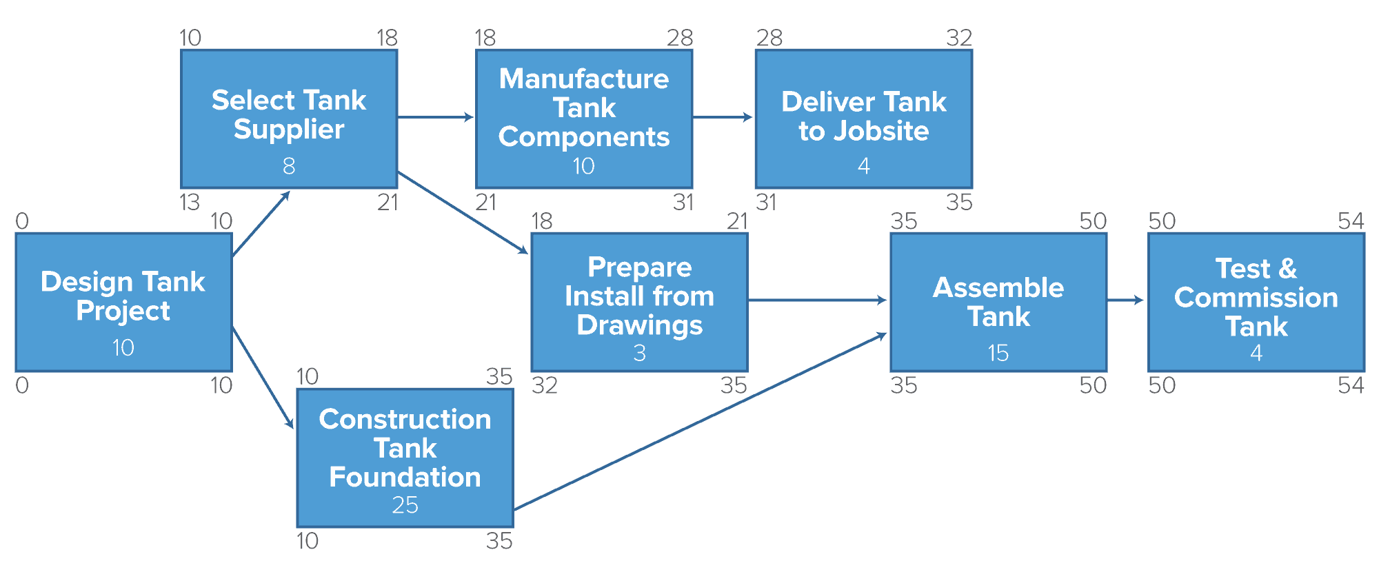
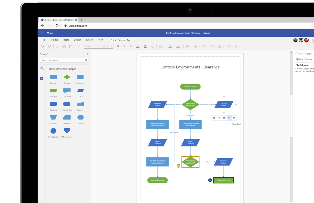
The title at the top of your network diagram grid is the same as what you named the file. If you want to change the name on the actual diagram, double-click the diagram title and type in a new name. If you'd like to adjust the font and type size, use the shortcut keys in the menu bar at the top of the screen.
To set up the equilibrium conditions, we draw a free-body diagram and choose the pivot point at the upper hinge, as shown in panel (b) of (Figure). Finally, we solve the equations for the unknown force components and find the forces. Figure 12.17 (a) Geometry and (b) free-body diagram for the door.

Engineering Drawing Basics Explained. An engineering drawing is a subcategory of technical drawings. The purpose is to convey all the information necessary for manufacturing a product or a part. Engineering drawings use standardised language and symbols. This makes understanding the drawings simple with little to no personal interpretation ...

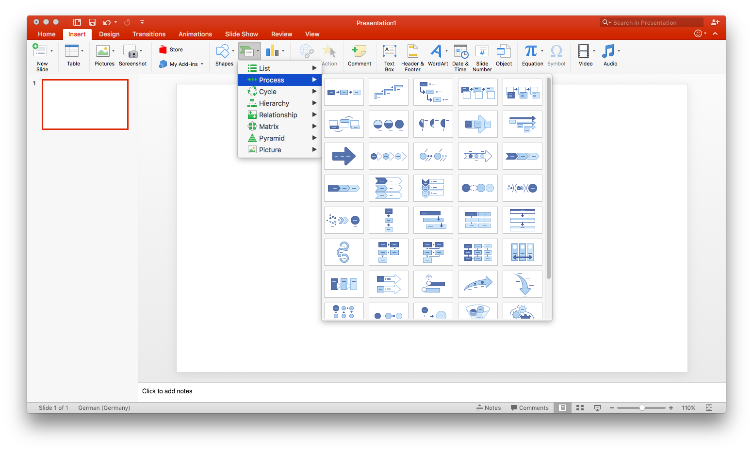
You can also try an animated diagram template, in which tabs are revealed one by one. Microsoft's animated diagram templates include an animated flower slide, an animated scale, and many others. Used alone or as part of a presentation, diagram templates give your story more impact to leave a greater impression on your audience.
Draw a top down diagram of your setup from part e this diagram should include. You dont have to rely on your employees remembering the extra steps of saving and storing the diagrams in an appropriate and central location. In your mind draw a boundary around the fish tank including the waterto define it as your system.

Page 21 CHAPTER 3 Part R Replaceme ent Guide 3.4 RUNN NING DEC K REPLAC CEMENT 1) Remove e the motor c cover as outl lined in Sect tion 3.1.
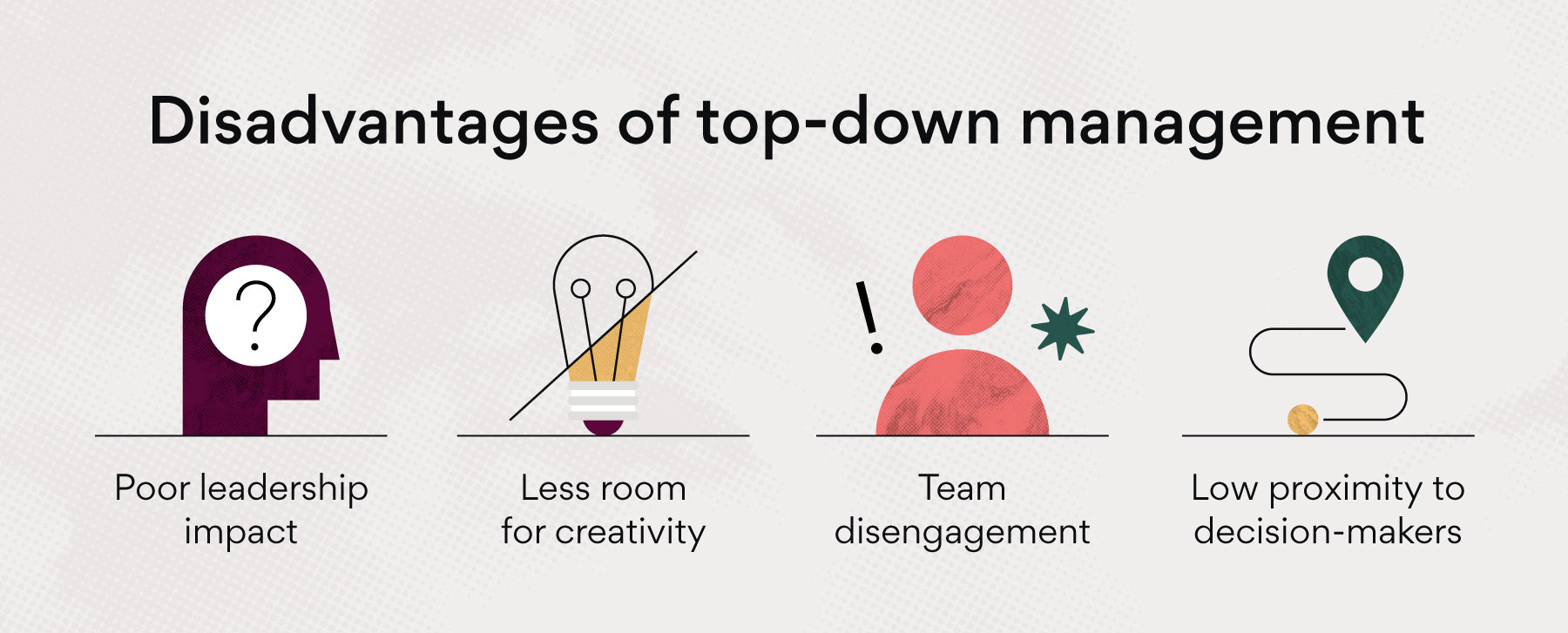
By seeing how the business works from a top-down perspective, you can identify it's potential flaws, weaknesses, and areas for improvement. On top of that, the workflow diagram can be extremely helpful for your employees, as a means of double-checking what needs to be done, who's responsible, etc.
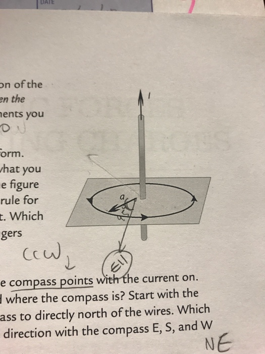
Draw a top-down diagram of your setup of image provided: I is current passing through wire arrows are vectors of compass pointing. Subject: Physics Price: 3.85 Bought 3. Share With. Draw a top-down diagram of your setup of image provided: I is current passing through wire arrows are vectors of compass pointing.

One of the many great parts of React is how it makes you think about apps as you ... In simpler examples, it's usually easier to go top-down, and on larger ...
desirable to draw the V-diagram below the FBD of the entire beam, and then draw the M-diagrambelow the V-diagram. The bending moment and shear force diagrams of the beam are composites of the V and M diagrams of the segments. These diagrams are usually discontinuous, or have discontinuous slopes.

A functional, top-down organizational chart reflects a traditional business structure. This structure shows the C-Suite at the top, followed by other senior management, middle managers, and so on. The structure is divided into traditional departments like IT, marketing, finance, human resources, and operations based on everyone's functional ...
The Model, View and Projection matrices. The Model matrix; The View matrix; The Projection matrix; Cumulating transformations : the ModelViewProjection ...
DATA (3):(a) Draw a top-down diagram of your setup of image provided: I is ... (N,S,E,W)Use your measurements from part E to calculate the strength of the ...

B - Starting at point #1, draw a diagonal line up to the left 5 intersections. (take your time and hit each diagonal intersection) C - Repeat step B for points 2, 3, 4, and 5. D - Now simply connect all 5 dots and your isometric view will be complete. STEP 4 STEP 5 LENGTH H E I G H T Front View 3" 2 " H E I G H T Top View 1 / 2 " 1 " 3 ...
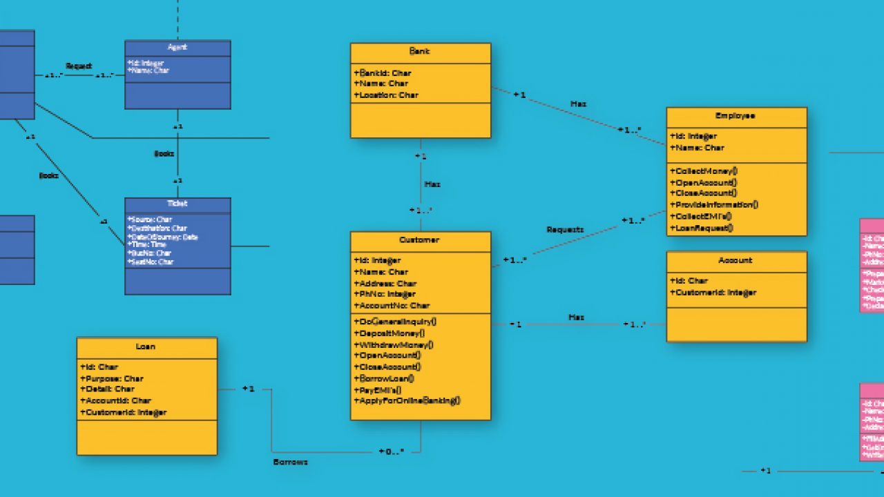
• An entity type E (or a relationship type R) has attributes representing the structural (static) properties of E (or R resp.). • An . attribute . A is a mapping from E (or R ) into a Cartesian Product of n values sets, V. 1 V. 2 … V. n . • If n 2 , then we call attribute A a . composite attribute, otherwise (i.e. when n=1) call it a

Transcribed image text: 1. (3.5) Draw a top-down 2D diagram of your setup in part E (imagine looking from above). This diagram should include a. The cardinal directions (N,S,E,W) b. The direction of current in the wires (8 for into, and O for out of the page) c. The direction of the compass needle (an arrow pointing to its north) d.
Setting Layer Add Option¶. You can set an option to always load new layers without drawing them. This means the layer will be added to the map, but its ...

4.0 Building Shear and Moment Diagrams. In the last section we worked out how to evaluate the internal shear force and bending moment at a discrete location using imaginary cuts. But to draw a shear force and bending moment diagram, we need to know how these values change across the structure.
i. Draw a diagram of the experimental setup of the board and block. In your diagram, indicate each quantity that would be measured and draw or state what equipment would be used to measure each quantity. ii. Describe the overall procedure to be used, including any steps necessary to reduce experimental uncertainty.
4.4 Moment Diagrams by Parts The moment-area method of finding the deflection of a beam will demand the accurate computation of the area of a moment diagram, as well as the moment of such area about any axis. To pave its way, this section will deal on how to draw moment diagrams by parts and to calculate the moment of such diagrams about
DATA (3): - Draw a top-down diagram of your setup of image provided: I is current passing through wire arrows are vectors of compass pointing.
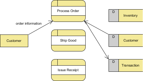
Which tool is used to draw ER diagram? Draw ER diagrams using templates, symbols, and notations. You can choose an automatic template called the Automatic ERD (Database) Diagram and generate your ER diagram using data from your database or choose one of the manual ERD templates included and design your database from scratch. Dbdiagram.
Many modern tow-capable trucks and SUVs, especially those by the Big Three, come equipped with trailer packages from the factory as part of the USCAR ...
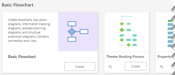
Online diagram software to create and securely share flowcharts, wireframes, UML models, network diagram and more. Start with a Free account!
The entire source code of yEd Lite, an only slightly stripped-down version of yEd, comes as part of the yFiles for Java library.
... and Operation Manual Safety Considerations 4 Troubleshooting 25 Specifications 5 Parts ... Crush And Screen Light Towers For Sale Mobile Crusher

If you're nearing maximum capacity for the venue, congratulations on your event's popularity. Banquet rounds will make the most efficient use of space. (Play around in a banquet table setup diagram to see how and why this is the case.) Take your robust guest list and seat them in staggered rows of round tables for maximum elbow room. 2.

We use cookies and comparable technologies to provide certain functions, to improve the user experience and to offer interest-oriented content.

... metallurgyThe working principle of cone crushers is explained to understand what application to best use the fine cone crusher in, diagrams of how a ...

Figure 5.32 (a) The free-body diagram for isolated object A. (b) The free-body diagram for isolated object B. Comparing the two drawings, we see that friction acts in the opposite direction in the two figures. Because object A experiences a force that tends to pull it to the right, friction must act to the left. Because object B experiences a component of its weight that pulls it to the left ...
There are a few golf club brands
ReplyDeletethat you may want to avoid if you're looking for quality clubs. Some of the brands to avoid include Callaway, Cleveland, and Wilson. These brands are often overpriced and don't offer the best quality clubs. You can find better quality clubs from other brands such as Titleist, Ping, and TaylorMade.