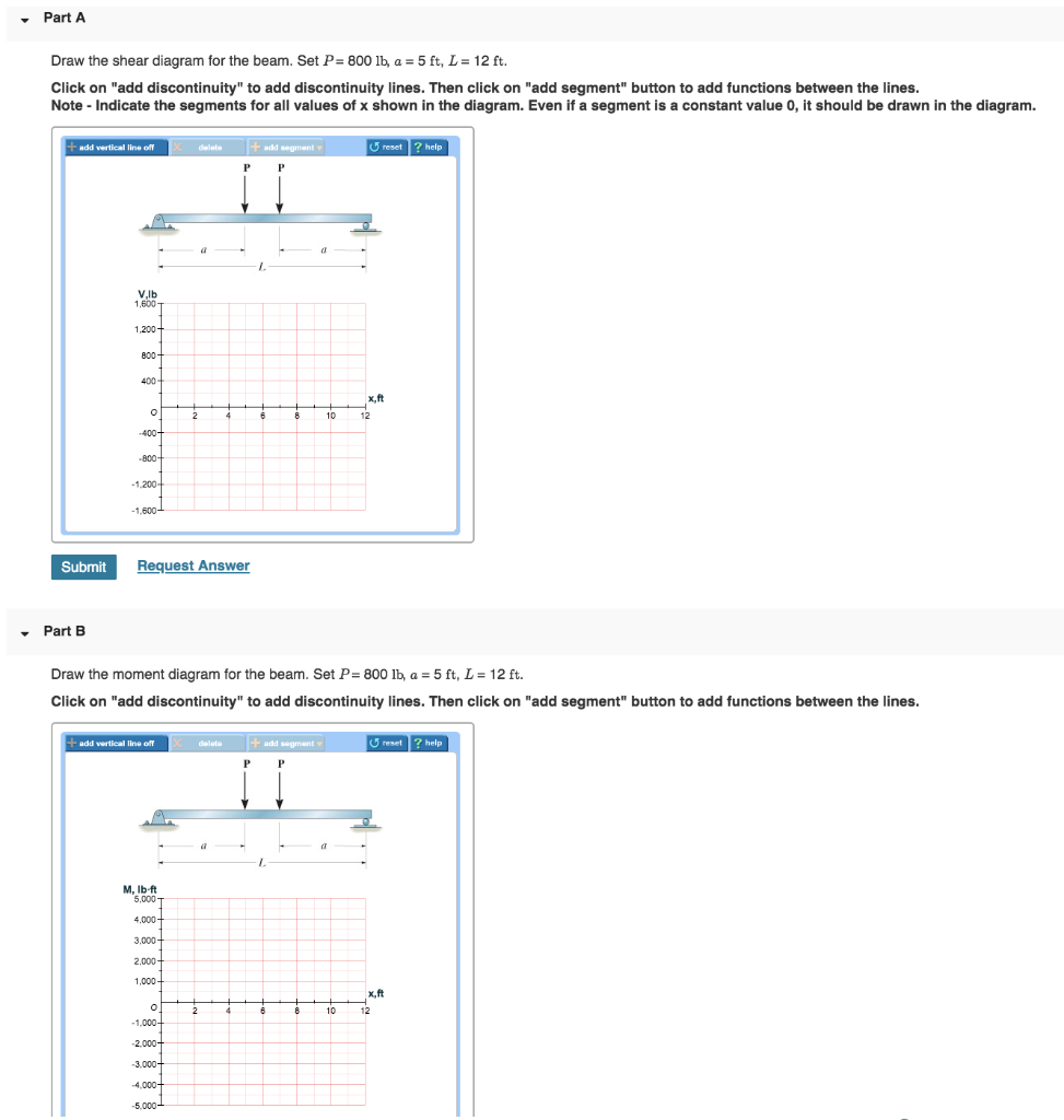
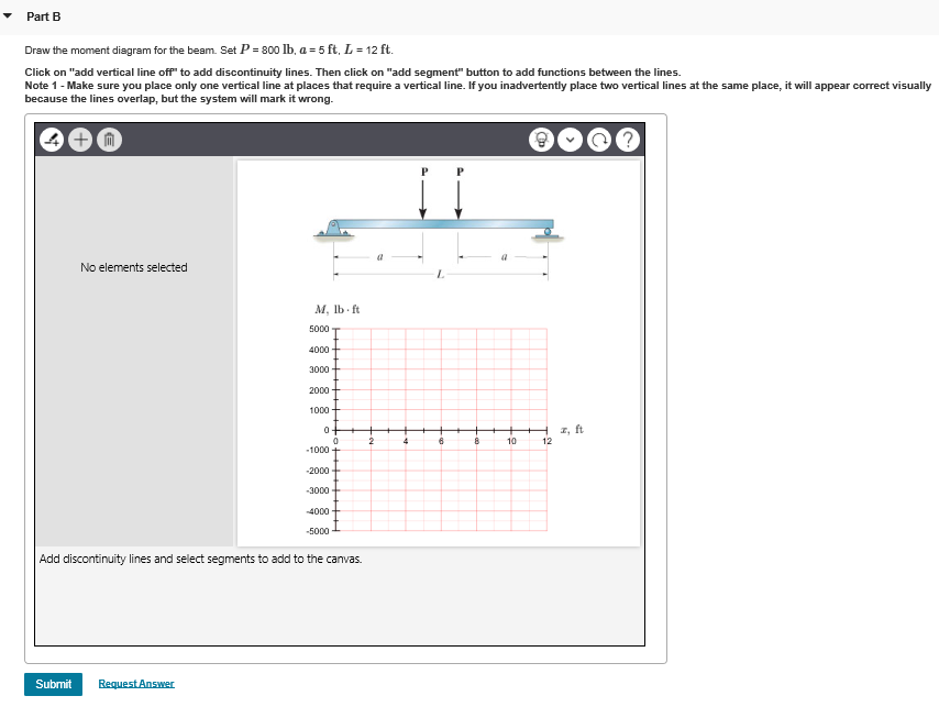
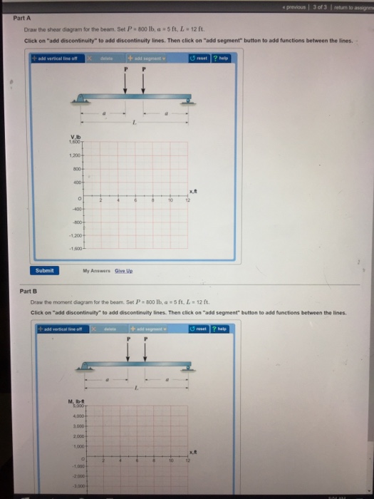
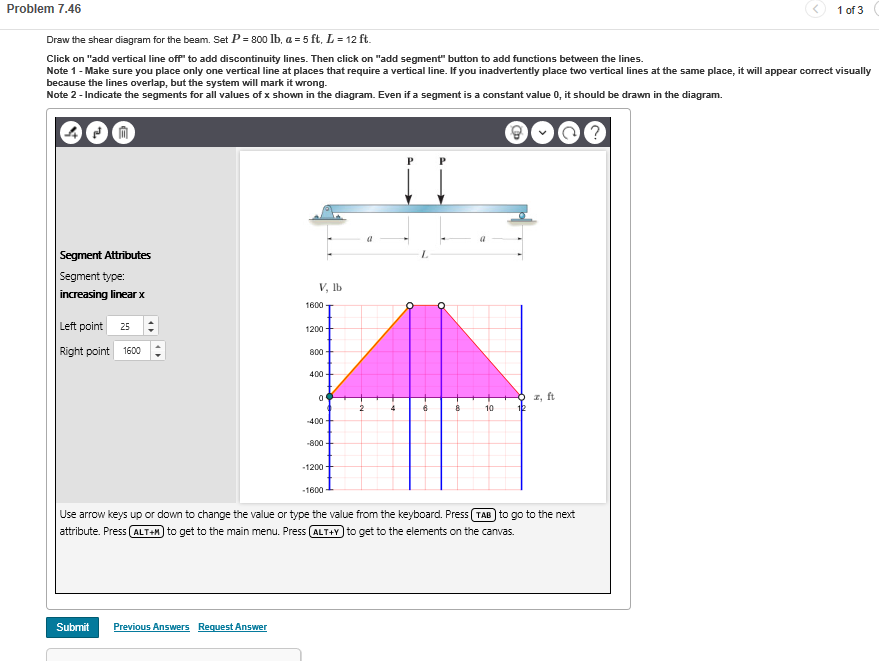
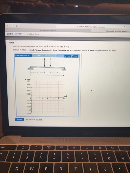
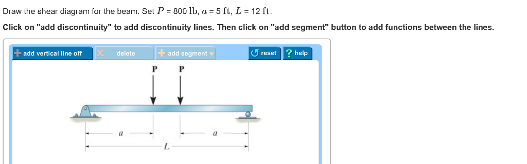
35 draw the shear diagram for the beam. set p = 800 lb, a = 5 ft, l = 12 ft.
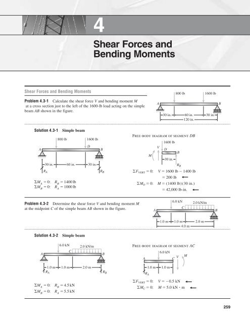
Draw the shear and moment diagrams for the beam, and determine the shear and moment throughout the beam as functions of x. 6 ft 4 ft 2 kip/ft 8 kip x 10 kip 40 kipиft A 30 kipиft B 5 ft 5 ft 2 kip/ft 5 ft 6-19. Draw the shear and moment diagrams for the beam. 06 Solutions 46060_Part1 5/27/10 3:51 PM Page 338 12. At x 2 ft vbc 800 lb. B set p 800 lb a 5 ft l 12 ft. To draw the shear diagram. Use the results to plot the shear and moment diagrams. In other words the line will be sloped. The distributed load applies a load at every single point that it covers so infinitely many shear decreases over any horizontal distance.
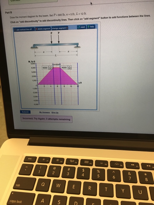
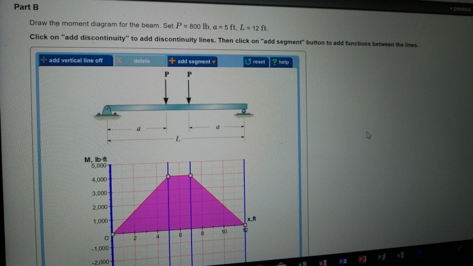
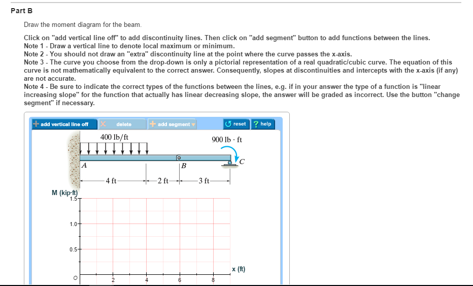
draw the shear diagram for the beam. set p = 800 lb a = 5 ft l = 12 ft › ... Draw the shear diagram for the beam . The diagram which represents the different effective force on the beam is known as shear and moment diagrams. As shown in figure. Draw the moment diagram for the beam.
Draw the shear diagram for the beam. set p = 800 lb, a = 5 ft, l = 12 ft.
(b) set P = 800 lb, a = 5 ft, L = 12 ft. Shear and Bending Moment Diagram A shear force diagram is used to denote the shear force at every point of a structure by considering all types of forces ... Shear and Moment Diagrams Consider a simple beam shown of length L that carries a uniform load of w (N/m) throughout its length and is held in equilibrium by reactions R1 and R2. Assume that the beam is cut at point C a distance of x from he left support and the portion of the beam to the right of C be removed. The portion removed must then be replaced by vertical shearing 6—25. Draw the shear and moment diagrams for the beam- The two segments are joined together at B. 8 kip 3 kip,ft 5 ft *6—20. Draw the shear and moment diagrams for the beam, and determine the shear and moment throughout the beam 10 kip 2 kip/ft g Kip 8 kip 40 kip.ft as functions of x. Support Reactions: As shown on FBD. Shear and Moment ...
Draw the shear diagram for the beam. set p = 800 lb, a = 5 ft, l = 12 ft.. The beam consists of two segments pin connected at b. Set p 800 lb a 5 ft l 12 ft. B set p 800lb a 5ft. In this case 2 lbft. Draw the shear and moment diagrams for the beam a in termsof the parameters shown. If l 10 ft the shaft will fail when the maximum moment is m max 5 kip ft. 8 ft 6 ft 6 ft 6 ft UNITS: P in lb M in lb-ft Free-body diagram of section AC Numerical value of M equals 640lb-ft. and P 1200 lb ∴ 640 lb-ft 8P 15 lb-ft M 8P 15 lb-ft M 4P 5 (6 ft) 4P 9 (12 ft) 0 ©M C4 0 9 A EP B CD Cable 8 ft 6 ft 6 ft 6 ft P __ 9 __4P P A P C 6 ft B 6 ft P __ 5 5 N M V __ 9 4P 4P 3P Problem 4.3-12 A simply supported beam ... Roof: Snow +DL = 200 lb/ft Walls: 400 lb on 2nd floor beams Railing: 100 lb on beam overhang Second Floor: DL + LL = 300 lb/ft (including overhang) Roof: Second Floor: , and evaluate the shear stress. *Also select the most economical steel section for the second-floor when 3Sreq'd ≥ 165 in and evaluate the shear stress when V = 60 k. Problem 406 Beam loaded as shown in Fig. P-406. [collapse collapsed title="Click here to read or hide the general instruction"]Write shear and moment equations for the beams in the following problems. In each problem, let x be the distance measured from left end of the beam. Also, draw shear and moment diagrams, specifying values at all change of loading positions and at
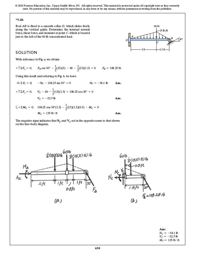
Set P=800 lb, a=5 ft, L=12 ft. Method of Area for Constructing the Moment Diagram of a Beam: Method of area is very useful when you have simple forces acting on a beam (e.g. force at a certain ... The load is F1 = 5-24i -10k6 lb, F2 = 5-80i6 lb, B and M = 5 -30k6 lb # ft. M 3 ft A C y F2 1.5 ft 2 ft x 7-35. Determine the x, y, z components of internal loading z at a section passing through point C in the pipe assembly. 5 A y = 2000 lb + ©M A = 0; F A = 4000 lb 4 F A(3) - 1200(8) = 0; 6-3. The engine crane is used to support the engine, which has a weight of 1200 lb.Draw the shear and moment diagrams of the boom ABC when it is in the horizontal position shown. 3 ft 5 ft B C 4 ft A The free-body diagram of the beam's right segment sectioned through an ... Shear and moment diagrams and formulas are excerpted from the Western Woods Use Book, 4th edition, and are provided herein as a courtesy of Western Wood Products Association. Introduction Notations Relative to "Shear and Moment Diagrams" E = modulus of elasticity, psi I = moment of inertia, in.4 L = span length of the bending member, ft.
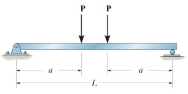
Draw the shear and moment diagrams for the simply supported beam. ... = 12 kN.mor MIX 4m 12kN .m . 4m 0 (b) M . 7—46. Draw the shear and moment diagrams for the ... If L = 18 ft, the beam will fail when the maximum shear force is V 800 1b, or the maximum moment is max 1200 1b .ft. Determine the largest intensity w of Draw the shear and moment diagrams for the beam (a) in terms of the parameters shown; (b) set P = 800 lb, a = 5 ft, L = 12 ft. a a L 582 7 Solutions 44918 1/27/09 10:39 AM Page 583 © 2010 Pearson Education, Inc., Upper Saddle River, NJ. Mechanical Engineering questions and answers. Draw the shear diagram for the beam. Set P = 800 lb, a = 5 ft. L = 12 ft. Click on "add discontinuity" to add discontinuity lines. Then click on "add segment" button to add functions between the lines. Draw the moment diagram for the beam. EXAMPLE 6.5 Draw the shear and moment diagrams for the beam shown in Fig. 6 -8a. Solution Support Reactions. The distributed load is divided into triangular and rectangular component loadings and these loadings are then replaced by their resultant forces.The reactions have been determined as shown on the beam's free-body diagram, Fig. 6-8b.
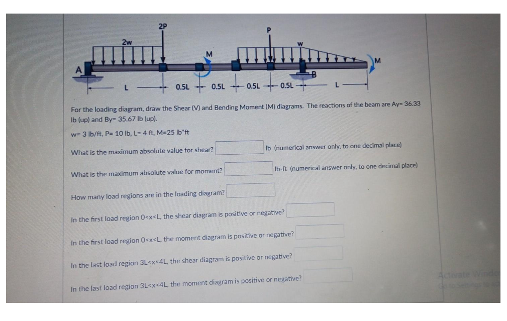
Draw the shear and moment diagrams for the beam and determine the shear and moment in the beam as functions of x, where 4 ft < x < 10 ft. View Answer. Draw the shear and moment diagrams for the beam (a) In terms of the parameters shown; (b) Set P = 800 lb, a = 5ft, I =12ft. View Answer. Draw the shear and moment diagrams for thebeam.
Draw the shear and moment diagrams for the double overhanging beam. 3 ft 3 ft 200 lb/ft 400 lb 6 ft 400 lb A B M (lb ft) x (ft) V (lb) 0 400 0 12 x (ft) 600 1200 1200 300 600 400 3 6 369 12 9 Ans: Hibbeler_Chapter 6_Part 1 (487-517).qxd 2/12/13 11:07 AM Page 499
A reinforced concrete pier is used to support the 60 kN 35 kN 35 kN 35 kN 60 kN stringers for a bridge deck. Draw the shear and moment 1 m 1 m 1.5 m 1.5 m 1 m 1 m diagrams for the pier when it is subjected to the stringer loads shown. Assume the columns at A and B exert only vertical reactions on the pier.
Problem 412 Beam loaded as shown in Fig. P-412. [collapse collapsed title="Click here to read or hide the general instruction"]Write shear and moment equations for the beams in the following problems. In each problem, let x be the distance measured from left end of the beam. Also, draw shear and moment diagrams, specifying values at all change of loading positions and at
Free online beam calculator for generating the reactions, calculating the deflection of a steel or wood beam, drawing the shear and moment diagrams for the beam. This is the free version of our full SkyCiv Beam Software. This can be accessed under any of our Paid Accounts, which also includes a full structural analysis software.
Consider a beam modeled by two beam elements (do not include shear deformations): Assume the EI to be constant throughout the beam. A force of 1,000 lb and moment of 1,000 lb-ft are applied to the mid-point of the beam. Beam Stiffness Step 5 - Assemble the Element Equations and Introduce Boundary Conditions The beam element stiffness matrices ...
Axial Force, Shear Force and Bending Moment Diagrams for Plane Frames Previous definitions developed for shear forces and bending moments are valid for both beam and frame structures. However, application of these definitions, developed for a horizontal beam, to a frame structure will require some adjustments.
Drawing Forces in the Beam: 12. Draw a diagram of the shear force in the beam. The shear in the end of the beam starts out at 0 lbs. However, since there is a reaction of 22,500 lbs on the left side of the beam, it will create that much shear in that location. The line load will cause this shear to decrease along the length
section of a beam : draw a free-body diagram that expose these ... w/x = 360/12, or w = 30x lb/ft. Part 2 The location of the section where the shear ... 5(8.165)3 = 5443 lb· ft =1000 −15x2 =0 dx dM. 4.4 Area Method for Drawing Shear- Moment Diagrams Useful relationships between the loading, shear force, and bending moment can be derived ...

Calculate the shear force and bending moment for the beam subjected to an uniformly distributed load as shown in the figure, then draw the shear force diagram (SFD) and bending moment diagram (BMD). 5 kN/m 3 m A B EXAMPLE 6
6—25. Draw the shear and moment diagrams for the beam- The two segments are joined together at B. 8 kip 3 kip,ft 5 ft *6—20. Draw the shear and moment diagrams for the beam, and determine the shear and moment throughout the beam 10 kip 2 kip/ft g Kip 8 kip 40 kip.ft as functions of x. Support Reactions: As shown on FBD. Shear and Moment ...
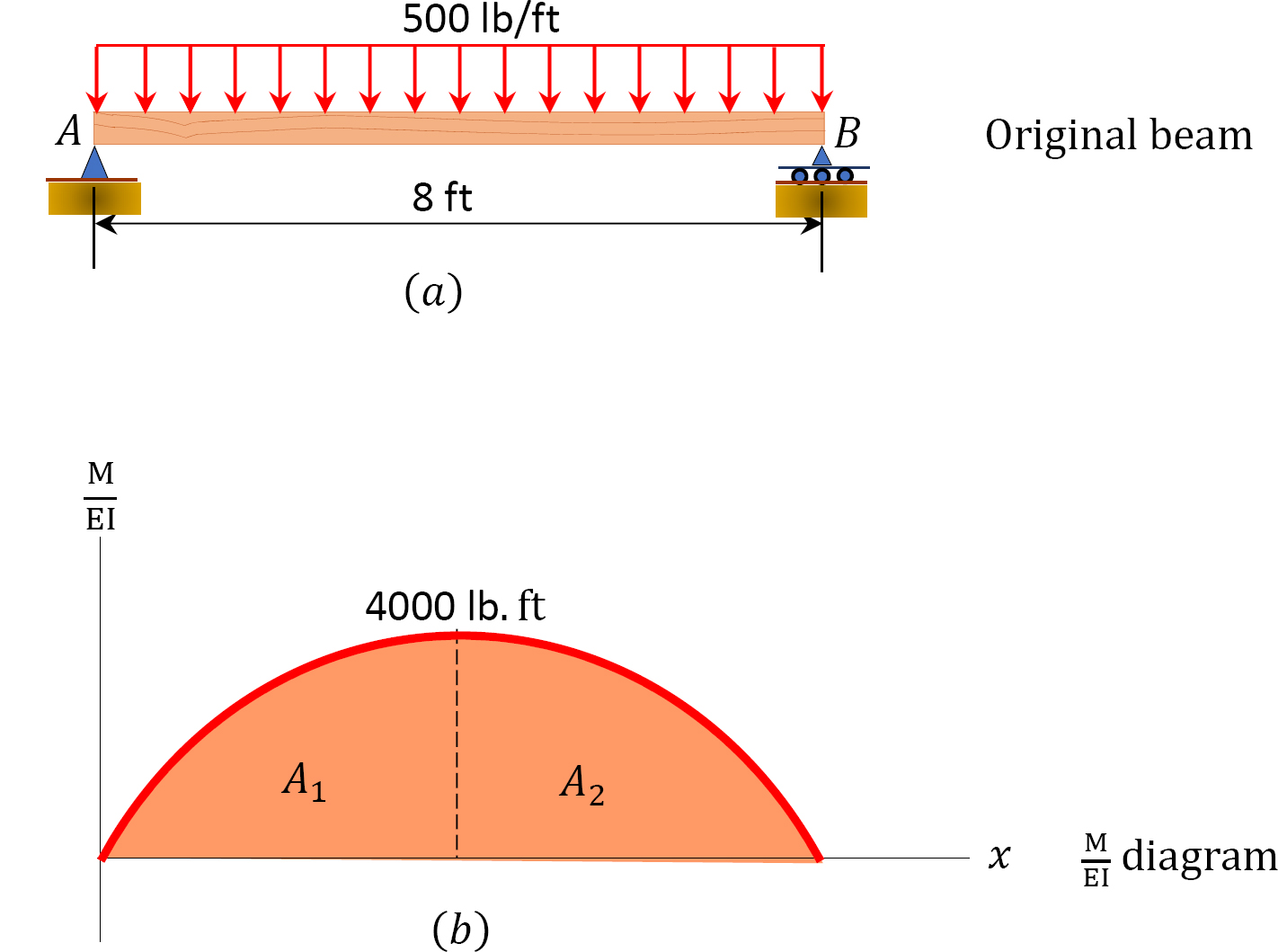
Shear and Moment Diagrams Consider a simple beam shown of length L that carries a uniform load of w (N/m) throughout its length and is held in equilibrium by reactions R1 and R2. Assume that the beam is cut at point C a distance of x from he left support and the portion of the beam to the right of C be removed. The portion removed must then be replaced by vertical shearing
(b) set P = 800 lb, a = 5 ft, L = 12 ft. Shear and Bending Moment Diagram A shear force diagram is used to denote the shear force at every point of a structure by considering all types of forces ...


0 Response to "35 draw the shear diagram for the beam. set p = 800 lb, a = 5 ft, l = 12 ft."
Post a Comment