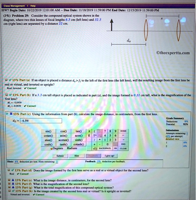
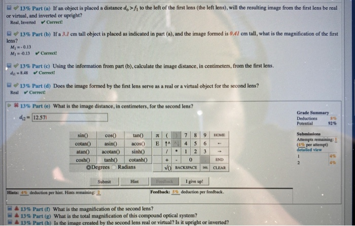
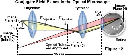
35 consider the compound optical system shown in the diagram
Integral regularities in the growth of 7YSZ thermal barrier coatings during MO CVD (Metal-Organic Chemical Vapor Deposition) are proposed. Within the framework of the model of the reacting boundary layer, the coating deposition process is considered as a process of independent global reactions of diffusion combustion of Zr(dpm)4 and Y(dpm)3 under convection conditions on a permeable surface. 85) Problem 13: Consider the compound optical system shown in the diagram, where tWO thin lenses of focal lengths_ cm (left lens) and 33.5 cm (right lens) ...4 answers · Top answer: far question. We have three lenses with vocal links F one F to an F three. The distance ...
Absolute Configurations of Perspective Formulas. Chemists need a convenient way to distinguish one stereoisomer from another. The Cahn-Ingold-Prelog system is a set of rules that allows us to unambiguously define the stereochemical configuration of any stereocenter, using the designations 'R ' (from the Latin rectus, meaning right-handed) or ' S ' (from the Latin sinister, meaning left ...

Consider the compound optical system shown in the diagram
In absence of atmosphere, the colour of sky appears. A) blue B) black C) red D) yellow. 55. Assertion: Sky appears blue in the day time. Reason: White light is composed of seven colours. Click Here to download pdf. If you want Class 10 Science Term 1 Sample paper 2021-22 in Doc or word format, mention in the comments. Whay is the other name of negative acceleration. - 24022121 pk3636186 is waiting for your help. Add your answer and earn points. 9. Consider the following acid-catalysed reactions for the natural compound below. OH но" тон Compound A Compound B a) Write the molecular formula for compound A. (1 mark) b) Draw all possible st
Consider the compound optical system shown in the diagram. Nov 15, 2020 — Consider the compound optical system shown in the diagram, where two thin lenses of focal lengths 8.5 cm (left lens) and 5.5 cm (right lens) ...1 answer · Top answer: As per the given question, focal length of the lenses are (f1)=8.5cm(f_1)=8.5cm(f1)=8.5cm f2=5.5cmf_2=5.5cmf2=5.5cm Distance between the lenses ... These geometries have a significant impact on the shape a particular molecule can assume. Figure 2.3. 2: When carbon forms single bonds with other atoms, the shape is tetrahedral. When two carbon atoms form a double bond, the shape is planar, or flat. Single bonds, like those found in ethane, are able to rotate. A compound beam is subjected to the loads shown in Figure 3.13a. Find the support reactions at A and B of the beam. Fig. 3.13. Compound beam. Solution. Free-body diagram. The free-body diagram of the entire beam is shown in Figure 3.13b. Identification of primary and complimentary structures. Question: (11%) Problem 8: Consider the compound optical system shown in the diagram, where two thin lenses of focal lengths 5.5 cm (left lens) and 9.5 cm ...
Orthographic projection is a way of showing a three-dimensional (3D) object in two dimensions (2D). Explore the definition of orthographic projection, different views, measurements, and some examples. The use of nanofibers creates the ability for non-enzymatic sensing in various applications and greatly improves the sensitivity, speed, and accuracy of electrochemical sensors for a wide variety of analytes. The high surface area to volume ratio of the fibers as well as their high porosity, even when compared to other common nanostructures, allows for enhanced electrocatalytic, adsorptive ... Consider some of these weaknesses associated with visual inspection: An optical illusion where black dots seem to appear and disappear at the intersections of the white lines. Human Vision alone is undependable — Optical illusions such as those to the left can demonstrate just how unreliable the human eye can be. The goal is to optimize the system, so the beam size is the smallest at 100 mm away from the laser output. We will model this system using ray-based approach first. As shown in the earlier section, when using rays to model Gaussian beam, we need to know if the propagation is within the Rayleigh range or outside Rayleigh range.
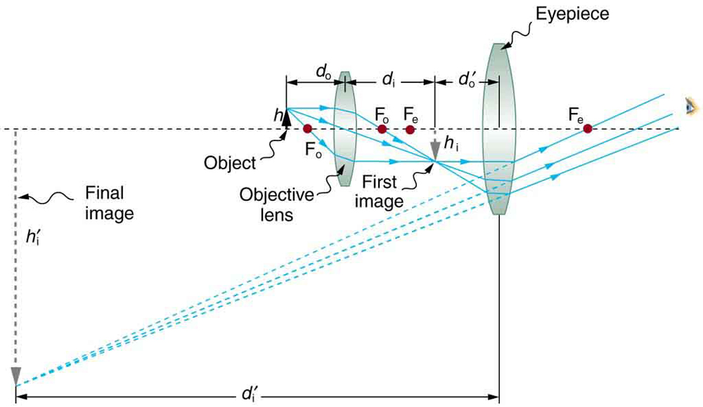
Consider the compound optical system shown in the diagram, where two thin lenses of focal lengths 7.5 cm (left lens) and 8.5 cm (right lens) are separated ...1 answer · 0 votes: a) using lens formula 1/f = 1/v - 1/u 1/7.5 = 1/ v + 1/15.3 v = 14.71 cm b) m1 = - v/u = - 14.71/15.3 = 0.9615 c) object distance for 2nd lens ... Draw a ray diagram in each of the following cases to show the formation of image, when the object is placed: (i) between the optical center and principal focus of a convex lens. (ii)anywhere in front of a concave lens. (iii)At 2F of a convex lens. State the signs and values of magnifications in the above-mentioned cases (i) and (ii). Ans. Image 2: The principle of a spectrophotometer as shown in the diagram above. Picture Source: encrypted-tbn0.gstatic.com Spectrophotometer principle. A spectrophotometer is a refined version of a colorimeter. In other words, it functions the same way as a colorimeter but with added features. Previous Post Previous Consider the compound optical system shown in the diagram, where two thin lenses of focal lengths 9.5 cm (left lens) Next Post Next 1. Scout says that the Radley place has ceased to frighten her.
This model supports ray trace analysis to identify and visualize potential aberrations that affect image quality in a CCM. As shown below, the assembly modeled in this tutorial has a 7.0 mm focal length and an f/2.4 focal ratio. An overview of the Compact Camera Module optical design.

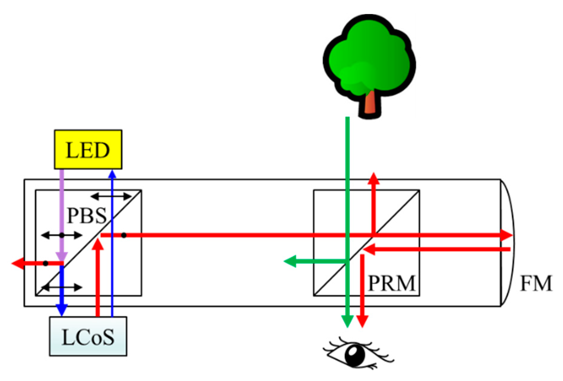
There is likely a quarter waveplate (not shown) that will cause the light reflected off the mirror to reflect off the beam splitter to the output. There are some other optical "tricks" that Lumus uses, so the above is an outline of the more obvious structures. Impressive Compound Photonics (CP) 2048 by 2048 LCOS microdisplay.

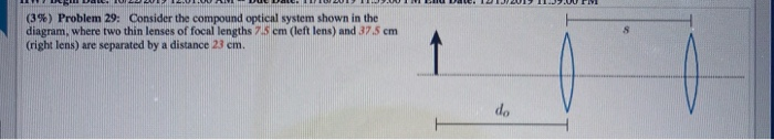
Answer to Consider the compound optical system shown in the diagram, where two thin lenses of focal lengths 7.5 cm (left lens) and 37.5 cm (right lens) are.2 answers · Top answer: Attached Attached Image transcriptions fo 1 2 do L2 Given, Focal length of louse LI = fy = 715cm Focal length of louse LZ = f, = 37.5 cm LIP Ly are seperated ...

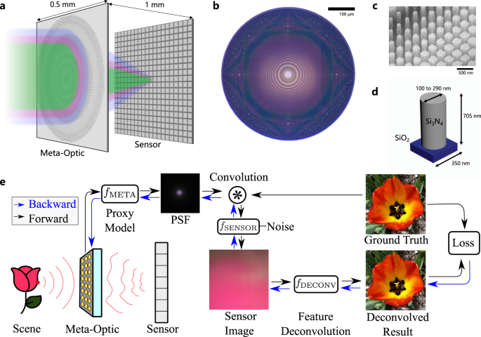
As a contrast, we consider the 4 f electrons as valence electrons to calculate the relative energy and partial DOSs of the same IS and FS1 structures in Fig. 4e, as shown in Supplementary Fig. 14.

The " Light Emitting Diode " or LED as it is more commonly called, is basically just a specialised type of diode as they have very similar electrical characteristics to a PN junction diode. This means that an LED will pass current in its forward direction but block the flow of current in the reverse direction.
Consider the spectrophotometric determination of iron(II) using the 1,10 phenanthroline complex. standards were prepared from a stock solution of iron(II). All measurements were made in a 1.00 cm cell

Figure created with biorender.com. Figure: Diagram of parts of a microscope. There are three structural parts of the microscope i.e. head, base, and arm. Head - This is also known as the body, it carries the optical parts in the upper part of the microscope.; Base - It acts as microscopes support. It also carries microscopic illuminators.

Wally blew 1/4 of his income last week on video games and 1/8 on fast food. If Wally spent a combined $84 on… Get the answers you need, now!

Introduction: A microscope is an instrument that magnifies an object so that it may be seen by the observer. Because cells are usually too small to see with the naked eye, a microscope is an essential tool in the field of biology.

(8%) Problem 12: Consider the compound optical system shown in the diagram, where two thin lenses of focal lengths 75 cm (left lens) and 40.5 cm (right ...1 answer · 0 votes: (e) do2 = 21 - 9.84 = 11.16 cm f2 = 40.5 cm Applying 1/f = 1/do + 1/di 1/40.5 = 1/11.16 + 1/di2 di2 = -15.4 cm So image distance = 15.4 cm left to the ...
Oct 6, 2021 — consider the compound optical system shown in the diagram, where two thin lenses of focal lengths 9.5 cm (left lens) and 42 cm (right lens) ...
The tail is transparent and thus is difficult to detect under a low power microscope. 23. Spirogyra under the microscope. Spirogyra is a green alga found mostly in freshwater in the form of green clumps. Spirogyra is unicellular, but because it clumps together, it can be seen in the pond even with our naked eyes.
Optical isomerism. Optical isomers are named like this because of their effect on plane polarized light. Simple substances which show optical isomerism exist as two isomers known as enantiomers. A solution of one enantiomer rotates the plane of polarisation in a clockwise direction. This enantiomer is known as the (+) form.

Fig. 9.8. Compound beam. Solution. Shown in Figure 9.8c through Figure 9.8g are the influence lines for the desired functions. The schematic diagram of the member interaction shown in Figure 9.8b immeasurably aids the initial perception of the range of the influence line of each function. Construction of the influence lines follows the ...

See the question and answers. Mathematics, 22.11.2021 08:30. Suppose that samples of size are selected at random from a normal population with mean 100 and standard deviation 10. What is the probability that the sample mean falls in the inte...
Ultraviolet-visible (UV-Vis) spectroscopy is a widely used technique in many areas of science ranging from bacterial culturing, drug identification and nucleic acid purity checks and quantitation, to quality control in the beverage industry and chemical research. This article will describe how UV-Vis spectroscopy works, how to analyze the output data, the technique's strengths and limitations ...
The best way to test is to repeat the ray-trace analysis using the NURBS component. For example, consider an even-aspheric lens, consisting of a surface with a conic asphere with added r 4 and r 6 terms. This is a very common aspheric element: As you can see from the Spot Diagram analysis, the lens is clearly diffraction limited.

Introduction of ER Model. ER Model is used to model the logical view of the system from data perspective which consists of these components: Attention reader! Don't stop learning now. Practice GATE exam well before the actual exam with the subject-wise and overall quizzes available in GATE Test Series Course.
9. Consider the following acid-catalysed reactions for the natural compound below. OH но" тон Compound A Compound B a) Write the molecular formula for compound A. (1 mark) b) Draw all possible st
Whay is the other name of negative acceleration. - 24022121 pk3636186 is waiting for your help. Add your answer and earn points.

In absence of atmosphere, the colour of sky appears. A) blue B) black C) red D) yellow. 55. Assertion: Sky appears blue in the day time. Reason: White light is composed of seven colours. Click Here to download pdf. If you want Class 10 Science Term 1 Sample paper 2021-22 in Doc or word format, mention in the comments.


0 Response to "35 consider the compound optical system shown in the diagram"
Post a Comment