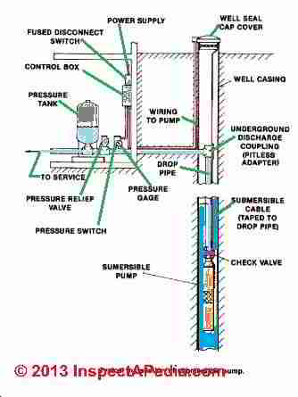
40 water pressure tank installation diagram
PDF INLINE PRESSURE BOOSTING SYSTEM - Lowe's Install inlet and outlet plumbing and pressure tank as shown in Figure 1. The inlet and outlet of the unit is marked with "INLET" and "OUTLET" respectively. Unions should be installed on the suction and discharge ends of the pump (use of PTFE thread sealant tape is recommended over paste; do not overtighten). How to Install a Water Heater Expansion Tank in 10 Steps 02.04.2022 · That is why you need a thermal expansion tank to prevent excess water pressure from damaging the water heater and other water appliances. It often works in tandem with the temperature and pressure (T&P) relief valve. Sizing a thermal expansion tank requires knowledge of water heater capacity. A 2-gallon thermal expansion tank is suitable for most …
Installation Manuals & Documentation - Pure Water Products Retention Tank Installation; Aeration. Aer-Max Aeration Tank Head Diagram; Aer-Max Control Options; Aer-Max Drain Tee Instructions; Aer-Max Installation Instructions ; Aer-Max Pump Cleaning Instructions; Single Tank Passive Aerator — Programming and Start-Up; Smart Vent Instructions; Reverse Osmosis. Installing a TDS Meter on your R12 RO unit; Ultraviolet. …
Water pressure tank installation diagram
PDF PRE-PRESSURIZED DIAPHRAGM TANK - Lowe's 2. Install tank as close as possible to the pump pressure switch to reduce friction loss and elevation difference between the tank, water supply main and switch. 3. After installation, be sure the pressure switch is set low enough to shut the pump off. If all valves are Installation, Operating, Maintenance and Safety ... Installation, Operating, Maintenance and Safety Instructions . ACCUMULATOR TANKS & EXPANSION TANKS in PRESSURISED WATER SYSTEMS . IMPORTANT PLEASE READ THESE INSTRUCTIONS CAREFULLY BEFORE INSTALLING OR USING YOUR ACCUMULATOR / EXPANSION TANK. FAILURE TO FOLLOW THE RECOMMENDED … Water Heater Piping Connections & Installation Guide to water heater or geyser installation: Water heater piping installation & connections: here we describe the plumbing connections and piping options for hot water system hook-ups. We explain the piping for a basic water heater installation compared with options for connecting hot water heaters in parallel, in series, or ganged.
Water pressure tank installation diagram. How Does Hot Water Recirculation Pump Work? #Diagram ... 13.01.2021 · A tankless water heater is also known as on-demand water heater. These make use of the high powered burners for heating the water rather rapidly. The tankless water heaters supply the hot water directly to your faucets without storing it. A traditional storage water heater, on the other hand, has an insulated tank. The tank capacity can range ... Water tank air bladder pressure settings: How to Set or ... Set the air pressure in the empty water tank to 2 psi below the well pump pressure switch cut-in pressure. Bleed air pressure out of the water tank, or add air pressure into the water tank, until the tank pressure is at the desired set-pressure.. PDF Booster Pump Installation Instructions Booster Pump Installation Instructions 1. Install pressure switch in tank line. (See diagram on back for where to place the pressure switch). 2. Pump must be located within 2 feet of pressure switch and within 6 feet of power outlet. A. Pump can be mounted to the wall horizontally in either direction or vertically only one way ~ with pump head and What is RO Water Purifier? Working, Diagram & Parts Detailed 12.10.2019 · The method uses water to create pressure, ... You do not need to add chlorine or softeners into the water tank anymore! By investing in the RO system, you reduce the need to purchase bottled water. It reduces the consumption of plastic widely and reduces the cost, as well. What we love the most about technology is how compact and easy-to-use it is. You can …
Pressure Tank Installation and Operating Instructions - Orion ... Cut-in PSI Cut-off PSI Pre-Charge Pressure 20 30 0 40 50 60 18 PSI 28 PSI 38 PSI 1. Lay carton on its side. 2. Open bottom flaps and pull tank just until hole in tank skirt is visible. 3. Install nipple, and/or Tank "T" and other required fittings. 4. Stand tank upright and lift off carton and protective bag. 5. Water Pressure Tank Install EASY DIY Plumbing - YouTube How to install well water pressure tank DIY Plumb pressure tank installation in 10 minutes. Save money Do It Your Self. Deep well pump sediment ruined your b... Well Pump & Pressure Tank Diagram - Clean Water Store 1. Check Valve Located at the top of the pump to prevent back flow into pump and hold the head of water in the system. 2. Torque Arrestor Installed directly above Submersible Pump to protect pump and well components from starting torque damage. 3. Safety Rope A safety line from the top of the well to the pump. 4. Conventional Pump & Pressure Tank Installation Diagram ... Conventional Pump & Pressure Tank Installation Diagram (Pitless Adapter) AWESOME DEALS!!! FREE SHIPPING on any order over $500.00 (Contiguous U.S.
Well Water Pressure, Pumps & Tanks - How It Works - YouTube Basic overview of a well water system and how it works with a softener and conditioning filter showing all the well componentsGood for new homeowner's who wa... Installation Manual DIAPHRAGM WELL TANK NO LEAD Install tank as close as possible to the pump pressure switch to reduce friction loss and elevation difference between the tank, water supply main, and switch. 3. After installation, be sure the pressure switch is set low enough to shut the pump off. PDF Installation Manual for Vertical Well System Tanks pressures (75 psig or more). This will protect the well tank and other system components should the pressure switch malfunction and fail to shut the pump off. The relief valve should be installed at the connection of the well tank to the system piping and have a discharge equal to the pump's capacity at 75 psig. At least once every 3 years Well Pressure Tank Installation | The Home Depot - YouTube This well pressure tank installation video shows the steps you'll need for this replacement. Be sure to follow the proper requirements listed below and in th...
Tank-Installation-and-Operation-Manual-M-MT1_EN.pdf ⚠ CAUTION: To prevent personal injury, ensure all water pressure is released from the pressure system prior to work being performed. Ensure pumps are ...2 pages
How a Well Pressure Tank Works - with Diagrams - Plumbing ... Water Pressure Tank Installation Diagram The image below shows the typical installation diagram of a well pressure tank, as well as other components of a well system. Image: Lakeland Water Pump How a Bladder Pressure Tank Works A bladder pressure tank is a steel tank with a bladder inside which looks like a balloon.
Well Pump & Pressure Tank Diagram - Well Water Report 1. Check Valve Located at the top of the pump to prevent backflow into the pump and hold the head of water in the system. 2. Torque Arrestor Installed directly above Submersible Pump to protect pump and well components from starting torque damage. 3. Safety Rope A safety line from the top of the well to the pump. 4. Pitless Adapter
Understanding Your Pressure Storage Tank | Nebraska ... The diaphragm is a membrane that separates the water and air in the tank. One way to select the proper size for a pressure tank is to base it on the pump's flow rate. A typical private water supply pump supplies water at a rate of 5 to 10 gallons per minute (gpm). Multiply the flow rate by four to determine the size of a diaphragm or bladder tank.
How a bladder pressure tank works - APS Water The first bladder will assure the pump has enough water on startup and the second bladder will store water just as in the above example. Trouble Shooting A Water Bladder Pressure Tank Pressure Bladders can be found here Economical Booster Pumps Can Be Found Here Contact Us 818-786-0600 Local/Int. 800-460-9011 Toll Free 818-786-2347 Fax
Rheem Performance 40 Gal. Tall 6 Year 40,000 BTU Natural ... The self-diagnostic gas control valve monitors system performance. A premium grade anode rod provides long lasting tank protection. Factory installed temperature and pressure relief valve and 3/4 in. water connections are included with the water heater for easy installation. This water heater is ENERGY STAR qualified.
Water Pressure Booster Pump Installation at Water Tanks ... This brief article outlines the basic installation layout for water pressure booster pumps coupled with back-up water tanks. Where possible, we recommend the use of both water pressure booster pumps and water tank stands. Water tanks on tank stands ensure there is always some pressure available, even in the event of a power failure.
Water Well Storage Tank Level Controls | Sensors | Float ... When that happens, malfunctions occur. Too little water means inadequate water pressure and potential dry running of equipment — both of which leads to expensive repairs to holding tanks and associated equipment. And all of this can be caused by sub-par sensors. Too many times, the traditional well water holding tank sensors are sub-par. Replace Potable Water Float Switches …

50 Water Well Pressure Tank Diagram Ms1g | Well pressure tank, Pressure tanks, Water well
PDF Installation Manual for Horizontal Well System Tanks ... Insert the pipe tee / nipple assembly in the female threaded opening on the tank inlet assembly from which you removed the boiler drain. Tighten hand tight, then wrench tight.
How to Install a Well Pressure Tank - Hunker Screw a pressure gauge into the opening on the top of the T. Place a pressure switch in the other opening atop the junction. Thread a female PVC connector onto each side of the T. One will go to the incoming water line and the other to the outgoing line. Test the pump by placing a tire gauge on the relief valve at the top of the tank.
DIAPHRAGM WELL TANK - AO Smith without water flow causing overheating and damage to the pump. 4. A pressure relief valve must be installed in the piping adjacent to the Well Tank.16 pages
Pvc Bulkhead Tank Fitting With Epdm Gasket - Buy Pvc Bulkhead Tank Fitting,Water Tank Adaptor ...
PDF Installation Manual DIAPHRAGM WELL TANK - Hot Water 2. Install tank as close as possible to the pump pressure switch to reduce friction loss and elevation difference between the tank, water supply main, and switch. 3. After installation, be sure the pressure switch is set low enough to shut the pump off. If all valves are closed and the pressure switch
Storage Tank Systems - Bee Cave Drilling A typical Bee Cave Drilling Well and Storage Tank System (with a steel sleeve wellhead) looks like the diagram below. When the water level in the storage tank drops about a foot from the top, the top float switch triggers the well pump to come on. The well pump pushes water up through the drop pipe to the surface and into the storage tank.
Diagrams --Typical Pump Installations - Water Pump Supply Diagrams --Typical Pump Installations The information provided here is for educational purposes only. Technically qualified personnel should install pumps and motors. We recommend that a licensed contractor install all new systems and replace existing pumps and motors.
How to Install Two Water Pressure Tanks Together | eHow Step 3. Install the pressure switch on the main water line running from the T down to the pumps. This should be installed on the main water line before the connection to the first pressure tank. In this way, if the first pressure tank needs to be isolated, the pressure switch will still be able to control the second pressure tank.
Pump Pressure Tanks, how they work and how to set them ... Install a pressure tank on the delivery side of the pump, as shown in the diagram. When this happens it creates a “balloon” of water that can build up in the tank. Once this volume has built up, then the pressure switch turns off and the water then pushes out into the line providing a more constant flow and pressure. Once the tank has pushed its contents out into the pipe, …




0 Response to "40 water pressure tank installation diagram"
Post a Comment