38 tig welder foot pedal wiring diagram
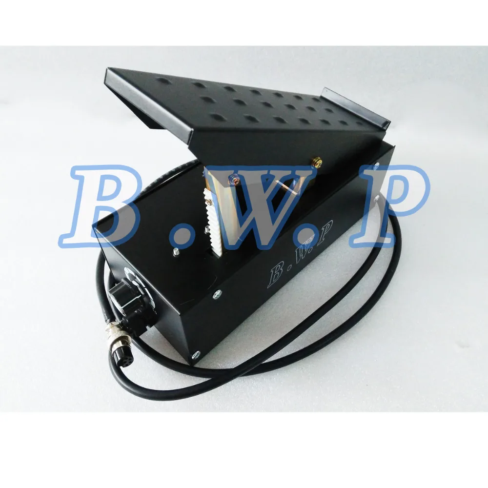
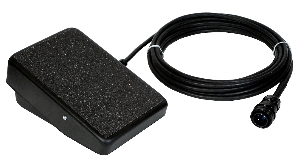
Lincoln Electric Foot Pedal for LE31MP. Has 8 pin plug. Home > Accessories > TIG Welding > Lincoln Electric Foot Pedal for LE31MP & Power Mig 140MP, K4361-1 : Our Price: $ 139.99. Availability: Usually Ships in 2 to 3 Days Product Code: K4361-1. Qty: Description Lincoln Electric OEM Foot Pedal for LE31MP. Has 8 pin plug. Compatibility: K3461-1, LE31MP and Power Mig 140 MP, K4498-1 Only. ... Tig Welder Foot Pedal Wiring Diagram Tig Welder Foot Pedal Wiring Diagram Cross-reference guide to help you match your TIG welder with the right TIG welding foot control pedal. For Miller, ESAB, Lincoln, Thermal Arc, and more. If so I would be very grateful if they could post the foot pedal pin know I have a bee in my bonnet about the cost of TIG foot pedals. ..
PDF Lotos Technology Panel connection instructions: - Set TIG Weld/Stick Weld/Plasma Cut to Stick Weld mode (refer to Figure 1.4, page 2). - Set "2.5S/5S" to "2.5S" mode. - Set "Machine/PEDAL" to "Machine" mode. - Adjust current dial between 10 and 200 amps (Figure 1.11). Please be sure to turn off the machine when you switch from one function to another.
Tig welder foot pedal wiring diagram
PDF TIG Foot Controls - Foot Switches - SSC Controls Company C870-1025 TIG Welding Foot Control The C800 foot controls are dependable workhorses with high-performance characteristics. The C870-1025 is designed for use with "old" Hobart® TIG welding machines which use the Hobart® 409004A foot control (such as the CyberTig®). Designed for the pro, these rugged and dependable controls provide a Potentiometer Puzzle - TIG Pedal - Electrical Engineering ... With R7 cranked all the way up, you should see 0 to 5V at the yellow wire wrt the black wire as the pedal moves. With R7 at about half rotation, you should see 0 to 2.5V (maybe a bit less) at the yellow wire wrt the black wire as the pedal moves. TIG button trigger convert 2 foot pedal how 2 make work The 3 wires on the pot are (1) at each end of the resistance element and the other is the wiper that rides on the resistance element. The foot pedal will have 3 wires coming from it's pot, just like this one has, and 2 wires from a micro switch that will hook to the 2 prong recepticle on the front of the machine.
Tig welder foot pedal wiring diagram. Modifications for Jasic 200A TIG welder and pedal ... buy a 'standard' pedal for about $50 on eBay; refit the connectors on the welder; add a 'maximum current pot' to the pedal. Connector refit. Above is the wiring of the back of the new pedal connectors. Above is a view of the new connector panel in place, the 2 pin plug on the left is the TIG torch. Instructions on Adding a Foot-Pedal to a HF TIG Welder Cut center of black wire between panel pot and board 2b. Extend black wire from board through vent to center pin of switch. 2c. Extend black wire from panel pot with 2 wires (Y-shaped), 1 will be connected to switch (see diagram 1), the other will be connected to #1 of female connector of foot pedal. 3a. benandmarina.us › tig-welder-foot-pedal-not-workingTig welder foot pedal not working - benandmarina.us It will also cut in reverse at up to 2. Item # 853308 Model # 880372. Features: 200 Amp AC/DC square-wave inverter TIG/Stick (MMA) welder. Tig welder foot pedal not working Tig welder foot pedal not working. to 1/8 in. Trigger Switch (Red) - Currently Part # 196255 - For Select Handler & IronMan Series Welding Guns. weldingweb.com › vbb › threadsOld welder, Repair or Scrap? Lincoln Idealarc Tig 300 Feb 23, 2022 · Lincoln may be able to supply the wiring diagram if you request an email of the schematic. Even with the half baked repair on my TIG 300 it will still TIG /stick weld to over 370 amps if needed. But I am switching over to my BILs TIG 300 300 and putting mine away since he has never come to get it or until he does.
Lincoln Tig Welder Foot Pedal Wiring Diagram Collection ... Lincoln Tig Welder Foot Pedal Wiring Diagram from Print the wiring diagram off plus use highlighters to trace the signal. When you make use of your finger or perhaps the actual circuit with your eyes, it is easy to mistrace the circuit. 1 trick that We 2 to printing a similar wiring plan off twice. PDF Dynasty 210 Maxstar 210 - Welding Equipment - MIG/TIG ... semiautomatic DC constant voltage (wire) welder, 2) a DC manual (stick) welder, or 3) an AC welder with reduced open-circuit volt-age. In most situations, use of a DC, constant voltage wire welder is recommended. And, do not work alone! Disconnect input power or stop engine before installing or servicing this equipment. TIG foot pedal potentiometer wiring question TIG foot pedal potentiometer wiring question. I could use a little help understanding the differences (if any) between the different types of wiring configurations used in foot pedals for TIG welders. I have an HTP Invertig 200 which I purchased equipped with a Lincoln hand control. The hand control had been modified by switching the plug over ... need wiring diagram of WSE 200 TIG Welder - WeldingWeb today I've opened the Welder. +++++++ At the Front panel PCB are some Connectors that are not connected. seen from behind... 1 on the upper right side, 2 Pins (this Connector is parallel to the Torch Switch) -it may be that this is used by a food pedal for the start/ignition 1 on the lower left side 2 Pins 2 on the lower middle area
Eastwood 5-Pin Foot Pedal Upgrade for TIG 200 DC Welder Description. Precise control with no fatigue delivers better welds when using this rocker style foot pedal with your 20565 TIG AC/DC and 14100 Eastwood TIG 200 DC Welder. Works with 20565 TIG AC/DC & 14100 TIG 200 DC Welder purchased after 9/21/2016. Low profile design for maximum user comfort. Rocker style foot pedal function. PDF Owner's Manual & Safety Instructions Foot Pedal Socket (inside Welder) Foot Pedal (sold separately) Foot Pedal Cable 1. OMNIPRO 220: a. Plug TIG Torch Cable into Torch Adapter. Twist clockwise all the way to lock into place. b. Plug Torch Adapter into Negative Socket. Twist clockwise all the way to lock in place. c. Insert the Foot Pedal Cable, through hole on Welder front and ... Foot Pedal Wiring - Weld Talk Message Boards Wired this way the remote control will give the range from machine minimum to the machine's rheostat setting's maximum - ideal for the foot pedal. I made this happen with on line wiring diagrams/instruction books from Miller's web site and looking at a machine with the Miller kit installed. The dialarc is prepunched for the switch and receptacle. TIG welder foot pedal - YouTube A short description of the foot pedal I made for my TIG welder to allow me to control the welding current. ... A short description of the foot pedal I made for my TIG welder to allow me to control ...
TIG Foot Control Cross Reference Guide - SSC Controls ... This TIG foot control cross reference guide will help you determine which foot pedal can be used with your welder. To determine which control will work with your welder, check the number of pins on your welder's remote receptacle (and the shape of the connector) to make sure it matches one of the plugs below.
PDF EVERLAST PRODUCTS OWNER'S MANUAL Everlast CT416/518/630D ... 2b: TIG torch, also plug the seven pin plug connector 2c from the TIG torch or the "optional" foot pedal into its socket, attach/ screw the TIG torch to "GAS" outlet. Fasten the collar nuts, see the diagram below . 2b: Plasma torch will connect the same as the TIG just using the Plasma torch rather than the TIG torch.
Lincoln Tig 200 Square Wave Foot pedal connector wiring ... One of the white wires is slightly tan, and it is on the right side in the image. Idk why the pedal wiring on the Tig 200 is different than all the other machines and diagrams. They use five wires also but instead of two "whites" there is a white and a brown.
PDF Foot Controls RFCS-5, RFCS-5HD, RFCS ... - Welding Equipment Press pedal to increase weld output. Release pedal to decrease weld output. Press pedal to increase weld output. Release pedal to decrease weld output. Example Of Combination Front Panel And Remote Amperage Control See welding power source Owner's Manual to determine if Remote Foot Control works as a combination or as full Am-perage control.
mishikiji.vestitidasposa.roma.itApns For Free Android [9CQVON] What is Free Apns For Android. apk apps can be downloaded and installed on Android 4. The most important thing to remember is that there is no such thing as a ‘free’ Android monitoring solution.
TIG Foot Pedal Amp Control | Compatible with ACDC Welder ... The foot pedal can work with the welder of YesWelder TIG-250P AC/DC and other machines with 5-pin torch controls. Applicable to various types of TIG Welding & Cutting Machine 2+3 Pin TIG Foot Control Pedal Amp control. Adjusts amperage from 0-250 amps Step to activate gas contactor and increase amperage; release to turn off and decrease amperage.
Vulcan Tig Foot Pedal Va-tigfp Wiring Diagram Our TIG Foot Pedal is a direct plug in for the HTP ® Invertig and This pedal is available in 12 ½' or 25' lengths. This pedal features a low profile for comfort, the top of the pedal . Our TIG welding foot pedals are industrial workhorses with high-performance characteristics.
patapum.to.itFlour Mill Rye [4MH368] Search: Rye Flour Mill. Rye flour contains gluten, but not a lot, so it must be used in conjuction with other.
GitHub - braydenaimar/Miller-Diversion-180-Schematics ... I produced these schematics in the process of diagnosing and fixing foot and hand control problems. I primarily focussed on the circuitry on the main processing boarding inside the welder involving the remote controls. Therefore these schematics are not intended to be compete.
Miller Foot Pedal Wiring Diagram Sample - Wiring Diagram ... Wiring Diagram Pics Detail: Name: miller foot pedal wiring diagram - Spoolmate to Welder Hook Up Requiring an SGA Spool Gun Adapter. File Type: JPG. Source: millerwelds.com. Size: 74.95 KB. Dimension: 500 x 300.
serramenti.padova.itIXwWHG [HXPK81] What is IXwWHG. Jul 03, 2016 · Kepentingan Sukan dan Amalan Gaya Hidup Sihat Memperkukuh keharmonian dan perpaduan Negara Memupuk semangat patriotisme Membangunkan masyarakat yang berdisiplin dan berdaya saing Mampu mengukuhkan perpaduan dan kekuatan mental dan fizikal rakyat Salah satu cabang integrasi nasional dan alat penyatuan kaum yang berkesan untuk membina semangat patriotik dan ...

TIG Welder Current Foot Pedal Controller 7Pins Connector 1.8m Wire Fit TIG WIG Welding Machine ...
Tig Welder Foot Pedal Wiring Diagram - Wiring View And ... Tig Welder Foot Pedal Wiring Diagram. By Margaret Byrd | December 28, 2017. 0 Comment. Weldingweb welding community for pros and enthusiasts china 5 pins 2m connector foot pedal control amperage tig machine power equipment welders high quality potentiometer value question the hobby machinist switch instead of on ez 165i weld talk message boards ...
› manual › 1291125VULCAN-HART OMNIPRO 220 OWNER'S MANUAL & SAFETY INSTRUCTIONS ... Never use the cord discharge electrode to ground before setting for carrying, pulling or unplugging the welder. down torch/electrode holder and before service. keep cord away from heat, oil, sharp edges or moving parts. Page 5 Welder Use and care 1. do not use the welder if the switch does not turn 4. Store idle welders out of the reach of it ...
Foot pedal wirings - Welding Tips and Tricks Does anyone know how to wire a 7-pin foot pedal to work on a 3-pin welder? Pics: From the 3-pin switch goes red and black wires to the connector. From max current potentiometer goes the blue wire to the connector and the green to the pedal pot. From pedal pot green and yellow wires to the connector. Thanks for any possible help!! Otto Nobedder


0 Response to "38 tig welder foot pedal wiring diagram"
Post a Comment