38 defrost timer wiring diagram
PDF 8000 MECHANICAL Series DEFROST TIMER - Everwell Parts Applications and Wiring Diagrams MECHANICAL DEFROST TIMER 8000 Series Customer Service Telephone 1.800.304.6563 Customer Service Facsimile 1.800.426.0804 HVACCustomerService@robertshaw.com ©2014 Robertshaw 09/14 - 150-2230 RevB For Technical Service Telephone 1.800.445.8299 Facsimile 1.630.260.7294 PDF Defrost Time Controls / HVAC/R - Neuco The defrost timer shall be housed in a UL Type 3R indoor/outdoor plastic enclosure. The relay output will be rated for 40 A Resistive, 2 HP @ 240 VAC. Defrost terminations to be by time (or by a remote temperature or pressure switch). For carry-over, the time controls shall have 2500-Hour reserve carry-over from a self-recharging battery.
PDF Defrost Timer Wire Diagram - bringit.corecreative.com Defrost Timer Wire Diagram Thank you definitely much for downloading Defrost Timer Wire Diagram.Most likely you have knowledge that, people have look numerous time for their favorite books past this Defrost Timer Wire Diagram, but stop occurring in harmful downloads. Rather than enjoying a fine ebook with a mug of coffee in the
Defrost timer wiring diagram
PDF Commercial Refrigeration Temperature and Defrost Controls The Latest Paragon® Defrost Timer • Universal Defrost Timers (UDT) • Works with multiple voltages • Removes built up of ice and frost • Easy to install • Simple to program • Part 9145-00 temp terminated • Part 9045-00 time terminated • Available as mechanism only without case - Add "M" to end of part number › manual › 2099568THERMO KING B-100 DIAGNOSTIC MANUAL Pdf Download | ManualsLib Section 3 - Software Description Defrost Mode Operation - All Units Defrost is initiated automatically by the programmable defrost timer, or manually by means of the In-cab Control Box. If demand defrost is enabled, a demand defrost cycle occurs, based on the Defrost Initiation Timer (DIT) and the Defrost Termination Switch (DK1 or DK2) being ... Walk In Freezer Defrost Timer Wiring Diagram At the condenser contactor, the defrost timer is wired in series with the high pressure switch and the low Me neither, even have some in freezers. Defrost Timer Controls. - Series Defrost Retail store walk-in coolers and freezers. • Boiler operating Typical line voltage wiring diagram. 3. Determine.
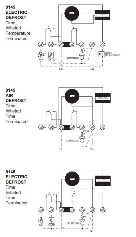
Defrost timer wiring diagram. PDF 9145 / 9045 UNIVERSAL Series DEFROST TIMERS DEFROST TIMERS An ISO 9001 - 2008 Certified Company Features and Benefits The Paragon® 9045-00 and 9145-00 Universal Defrost Timers are the only multi-voltage defrost timers engineered to refrigeration standards. At four defrosts per day, the Paragon Universal Defrost Timer switches last 16 years longer than competitive offerings. • Real ... Refrigerator Parts: Fast Shipping - Frigidaire Appliance Parts Refrigerator Parts - Shop online or call 888-343-4948. Fast shipping. Open 7 days a week. 365 day return policy. PDF Universal Electronic EDT11 DEFROST TIMER EDT21 DEFROST TIMER Universal Electr onic 3/4 H.P. 12-4609 and 12-9282. In these applications, use the SUPCO No. WH4, four-wire adapter harness kit if needed. Wire harness lead 1 to No. 3 of the original wiring, lead 2 to No. 4, lead 3 to No. 1, and lead 4 to No. 2. Original wire No 5 will not be used, it should be sleeved or taped and secured out of ... › diy › repair-guideHow to replace a dryer drum support roller | Repair guide Aug 01, 2014 · This DIY dryer repair guide explains how to install a drum support roller. The drum support roller holds the dryer drum in place as it turns. A damaged or worn support roller bearing typically makes a scraping or squealing noise, and the drum may make quick thumping sounds if the support roller has a flat spot.
Grasslin Dtav40 Wiring Diagram The DTAV40 defrost control automatically selects the appropriate voltage between Wiring Diagrams . Check your wiring, it sounds like it's not right. The wires on your new switch are intended for black = power.. white = neutral. and red = lights. First determine what model is being replaced (Grasslin or Competitors). Whirlpool Refrigerator Defrost Timer Wiring Diagram | vincegray2014 Whirlpool Refrigerator Wiring Diagram Pdf. Whirlpool Refrigerator Wiring Diagrams. Whirlpool Gold Refrigerator Diagram. Whirlpool Refrigerator Water Line Diagram. 3 Wire Defrost Termination Switch Wiring Diagram. 8 Pin Timer Relay Wiring Diagram. Ge Refrigerator Wiring Diagram Problem. Lg Inverter Refrigerator Wiring Diagram. Whirlpool Refrigerator Parts: Fast Shipping Whirlpool Refrigerator Parts - Shop online or call 844-200-5436. Fast shipping. Open 7 days a week. 365 day return policy. Paragon 8145 20 Defrost Timer Wiring Diagram - easywiring The paragon series auto voltage defrost timer is designed competitive voltage specific mechanical defrost timers eliminating wiring diagrams. 4 to minutes in s and paragon wiring diagrams electric heat defrosting s s series. Here is a picture gallery about 20 wiring diagram complete with the description of the image please find the image you need.
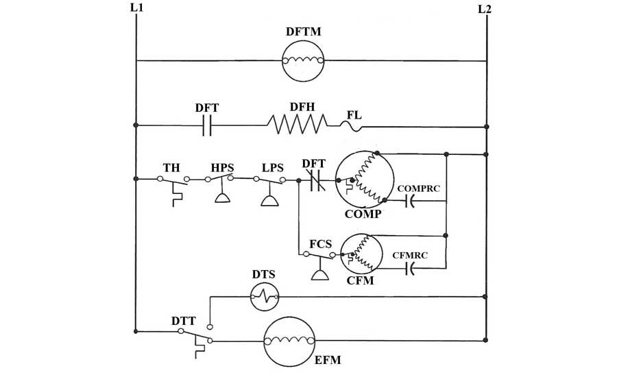
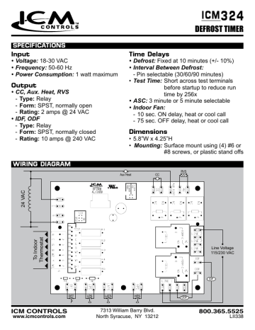
PDF Timer motor circuit DEFROST SYSTEMS timer only advances when the compressor is running. After the timer measures an accumulated run time equal to a predetermined amount, the system will enter into the defrost cycle. This type of defrost is often referred to as a cumulative run-time defrost. Even the cumulative defrost systems fail to account for the number of times the door is opened PDF Defrost Timer DEFROST TIMER SPECIFICATIONS WIRING DIAGRAM Input • Voltage: 18-30 VAC • Frequency: 50-60 Hz • Power Consumption: 1 watt maximum ... - Form: SPST, normally closed - Rating: 10 amps @ 240 VAC Time Delays • Defrost: Fixed at 10 minutes (+/- 10%) • Interval Between Defrost: - Pin selectable (30/60/90 minutes) • Test Time: Short across ... How to diagnose a Defrost time clock. Wiring and Troubleshooting ... In this video I will go over the Defrost time clock Wiring and Troubleshootinghttps:// PDF Commercial Refrigeration Defrost Controls - Supco Normally closed thermostat used with defrost heater. Wiring using 120V or 240V single phase line compressor voltage common to timer. CYCLE LIMIT SWITCH HEATER COMP THERMOSTAT Wiring Diagrams Electric Heat Defrosting S8141 & S8145 Series Wiring Diagrams Electric Heat Defrosting S8041 & S8045 Series THERMOSTAT THERMOSTAT THERMOSTAT N
INSTALLATION DATA 8000 SERIES AUTO VOLTAGE DEFROST TIMER
grasslin control defrost timer wire diagram - Wiring Diagram Line grasslin dtmv40 series timer operating intermatic dtav40 installation multi voltage defrost 40 the time controls hvac r mechanical switch programmable owner s manual no tools required snaps into existing auto t 49f wiring diagram swapping on heatcraft dtsz product catalog pages 101 commercial refrigeration temperature instructions for true part …
FIXED - FRT045GM Defrost Timer Question | Applianceblog ...
PDF WIRING DIAGRAM - AboveAir DEFROST TIMER WIRING DIAGRAM SPECIFICATIONS Input • Voltage: 18-30 VAC • Frequency: 50-60 Hz • Power Consumption: 1 watt maximum Output • O, W2: ... • Low cost defrost control DR = Defrost Relay Coil DFT = Defrost Thermostat LPS = Low Pressure Switch RVS = Reversing Valve Solenoid HPS = High Pressure Switch In-
Refrigerator Defrosting timer full connections and test timer in urdu/hindi
Wiring Diagram Frigidaire Defrost Timer 21546602 The instructions suggest comparing it with the wiring diagram of the freezer for proper hook up. Defrost Timer - 60Hz V - Frigidaire - Defrost timers are part of the defrost circuit in your refrigerator and freezer. The timer is connected into a wiring harness in the housing with a drain tube that goes into the back of the fridge.

I have an 8141 Paragon defrost timer and have to replace it ...
Typical Defrost Timer Wiring Diagram - wirinkgram.com On wiring diagram frigidaire defrost timer 21546602. Paragon 00 wiring diagram defrost timer circuit evaporator. If the timer has a white wire going to it ,the timer lead goes on #1 anything else goes on #2 Assortment of heatcraft walk in freezer wiring diagram. The orange wire goes to the thermostat and the red wire goes to the motors.
Sanyko Type Tmde706sa Refrigerator Defrost Timer - Buy Sanyko ...
Walk-in Freezer Defrost Timer Wiring Diagram One popular method of defrosting walk-in freezers is the electric defrost system. In a common wiring diagram for a time-initiated, temperature-terminated Normally closed contacts of the defrost timer are wired in series.Jul 01, · I am trying to install a defrost timer on a commercial freezer. It is a defrost-o-matic replacement.
FIXED - FRT045GM Defrost Timer Question | Page 2 ...
Lighting Contactor Wiring Diagram With Timer | vincegray2014 Lighting Contactor Wiring Diagram With Timer Free Download 2022 by dannie.bins. Find The BestTemplates at vincegray2014. vincegray2014. Menu; Home; About; Templates; Home. ... Paragon Defrost Timer Wiring Diagram. Schematic Ge Dryer Timer Wiring Diagram. Refrigerator Defrost Timer Wiring Diagram. Leave a Reply Cancel reply.
Precision Defrost Timers - Replacements Only
Walk In Freezer Defrost Timer Wiring Diagram In a common wiring diagram for a time-initiated, temperature-terminated Normally closed contacts of the defrost timer are wired in series. OUTDOOR WALK-IN COOLERS AND FREEZERS . Wiring Diagram - Freezer ½ to 2 HP Single Phase. .. Set the correct time of day on the defrost timer. Defrost Timer Controls.
How To Test the Defrost Timer - Refrigerator Repair Guide ...
Grasslin Defrost Timer Wiring Diagram Grasslin Defrost Timer Wiring Diagram The Grässlin DTAV40 Series Auto Voltage Defrost Timer is applicable to air defrost (compressor shutdown) and electric or hot gas defrost systems where the . MODEL G Series Mechanical Defrost Timer. Installation Instructions. Figure 2. Snapping tabs off mechanism. Figure 3. Installing the G Defrost Timer.

Whirlpool refrigerator defrost timer issue - DoItYourself.com ...
› Kenmore-Freezer-PartsOfficial Kenmore Freezer Parts | Order Today ... - PartSelect This is a 120 volt defrost timer manufactured for refrigerators. The defrost timer manages the automatic defrost systemin the unit. It acts like a clock by switching between activating the cooling cycle and the defrost heater to maintain the set thermostat temperature, preventing the unit from being too warm or cold.
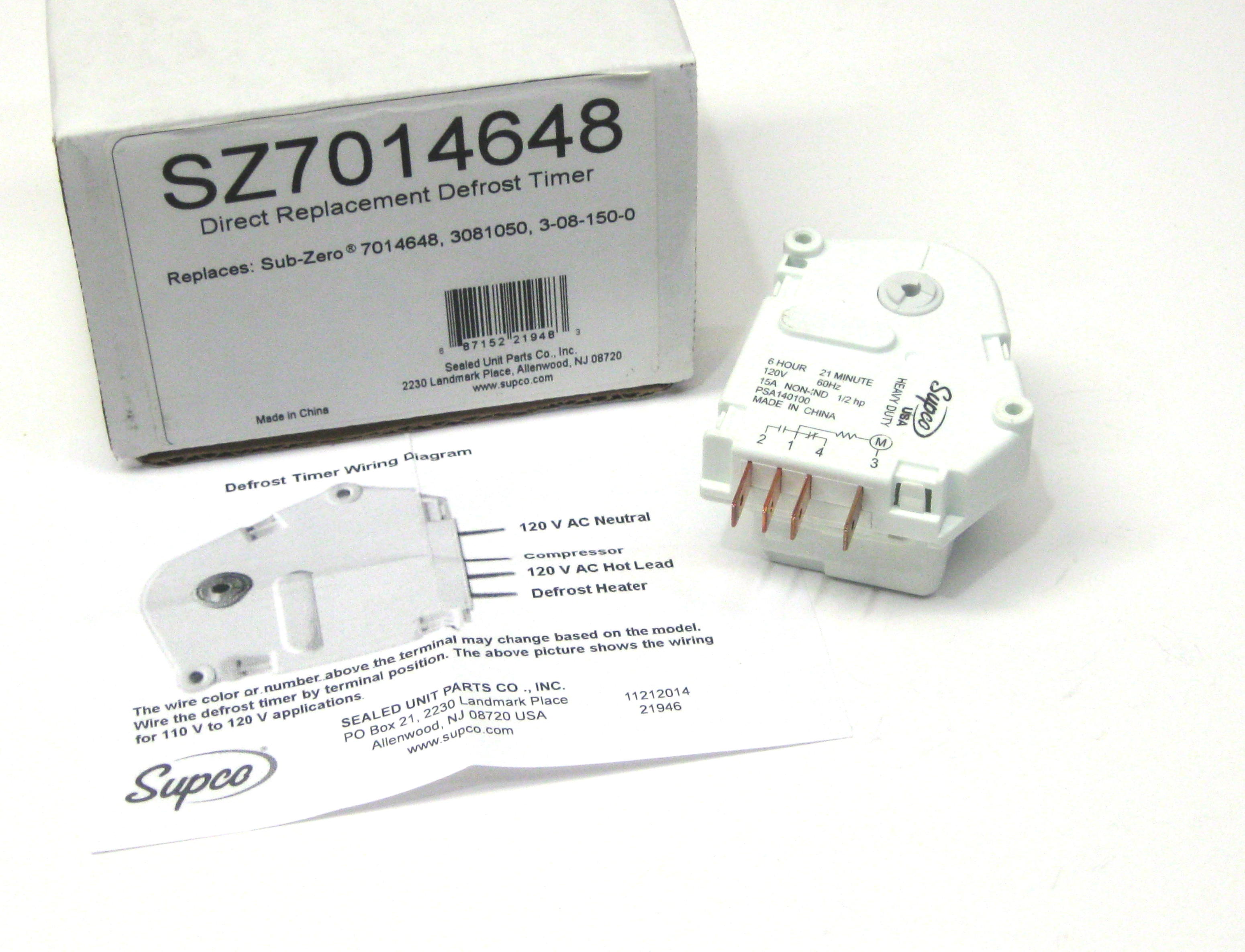
Supco SZ7014648 Refrigerator Defrost Timer Replaces Sub-Zero ...
PDF Installation & Operating Instructions DTAV40 Series Time ... - Baker Dist Follow this procedure to configure defrost times. 1. On the timer wheel, choose a defrost starting time. 2. Slide the tripper upward that is directly above the desired time. The timer will initiate a 15 minute defrost at the configured time. 3. To increase the duration of the defrost, slide up the trippers that are adjacent to the starting time.

Robertshaw | Products | A769-00
PDF Defrost Timers Defrost Timers. Catalog Number IRP Part . Number Volts 60 Hz. Switch type Paragon part : number Precision: Standard Pkg. Qty. Item Weights (lbs) BTT4100 460-0003: 120 2-NC/1-NO: ... Open Construction / Wire Leads: CATALOG : NUMBER IRP PART : NUMBER OUTPUT VA. PRIMARY V SECONDARY V: MARS JARD: Standard Pkg. Qty. Item Weights (lbs) TFM 2031 210 ...
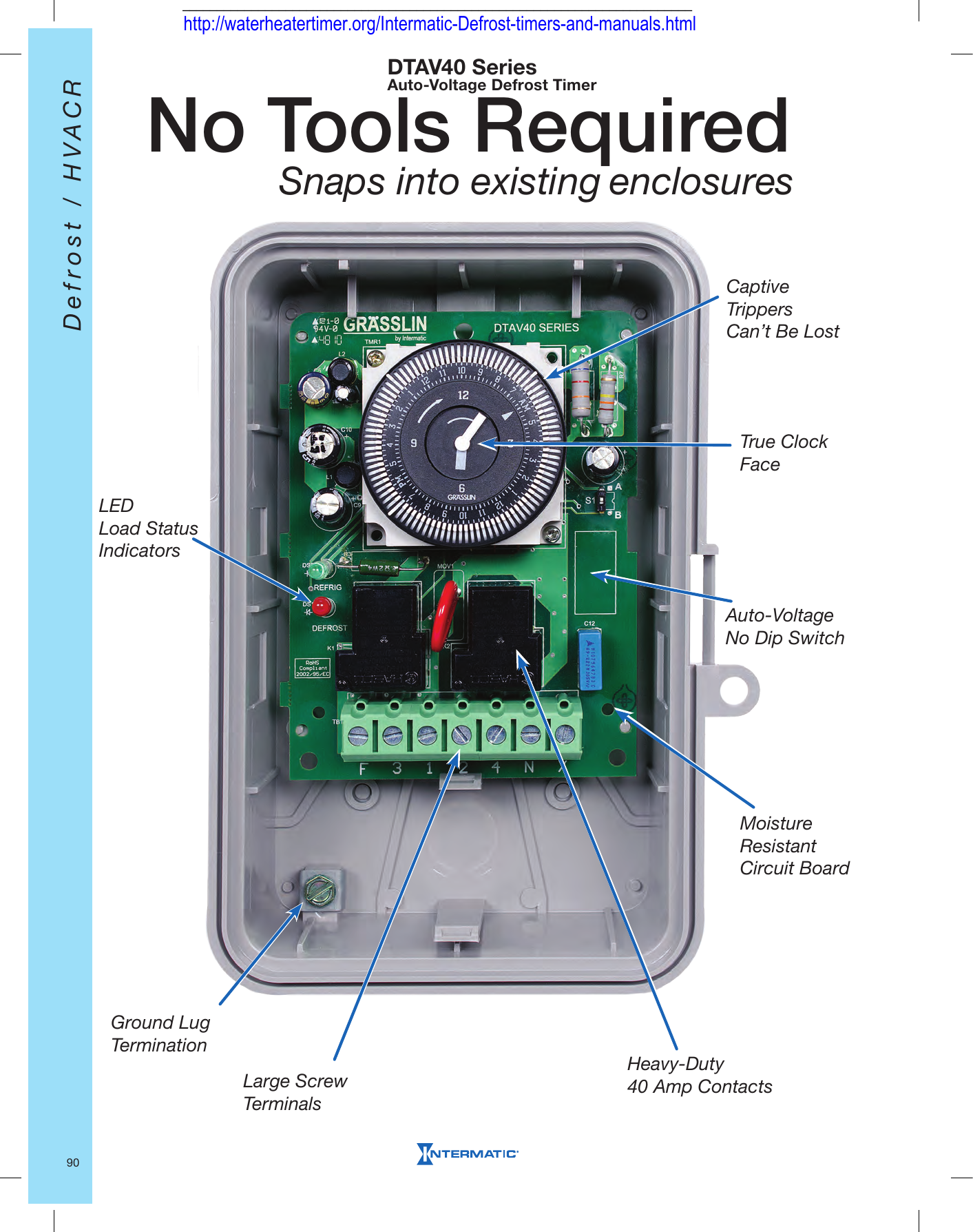
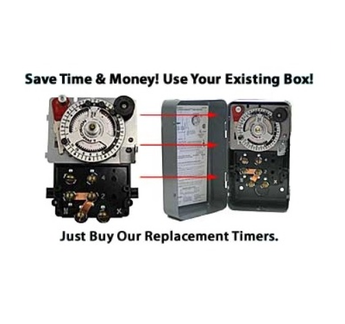
No Tools Required Snaps into existing enclosures
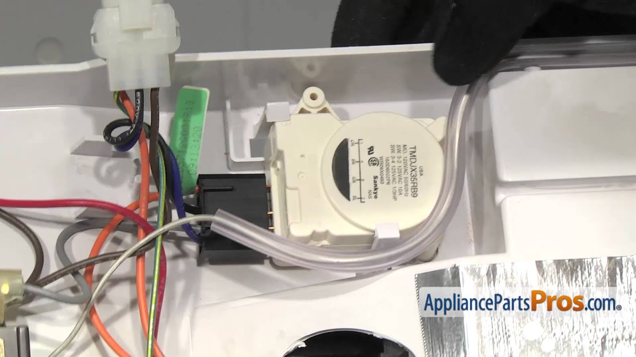
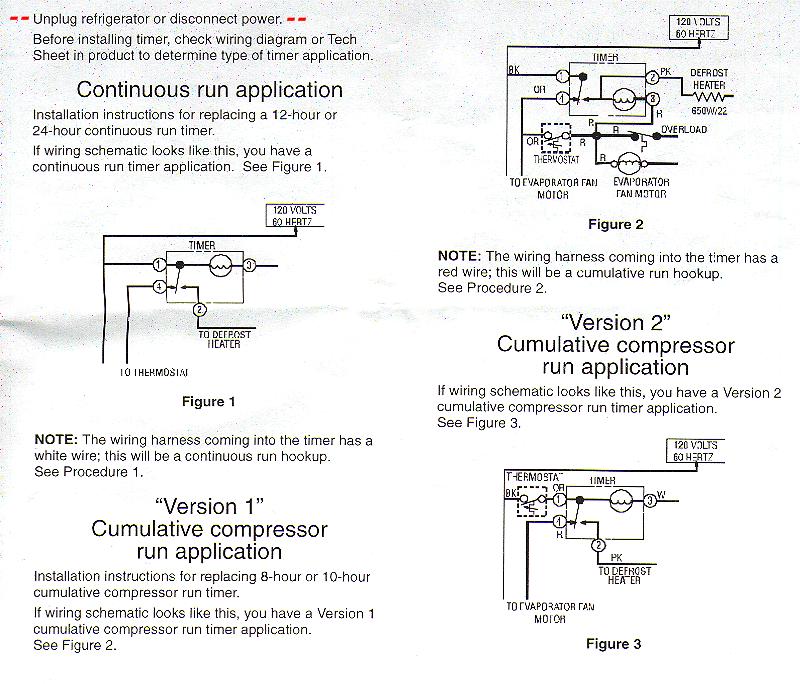
106.56622500 Where do I put the black wire terminal on a w10822278 ... Just need to know where to put the black wire on the timer. I'm following the instruction sheet. Proc 1 if a continuous run application, Proc 2 if cumulative compressor application and Proc 3 if Ver 2 Cumulative compressor run application. Sears parts direct say they dont carry the service sheet 2255373 any longer, which has a wiring diagram.
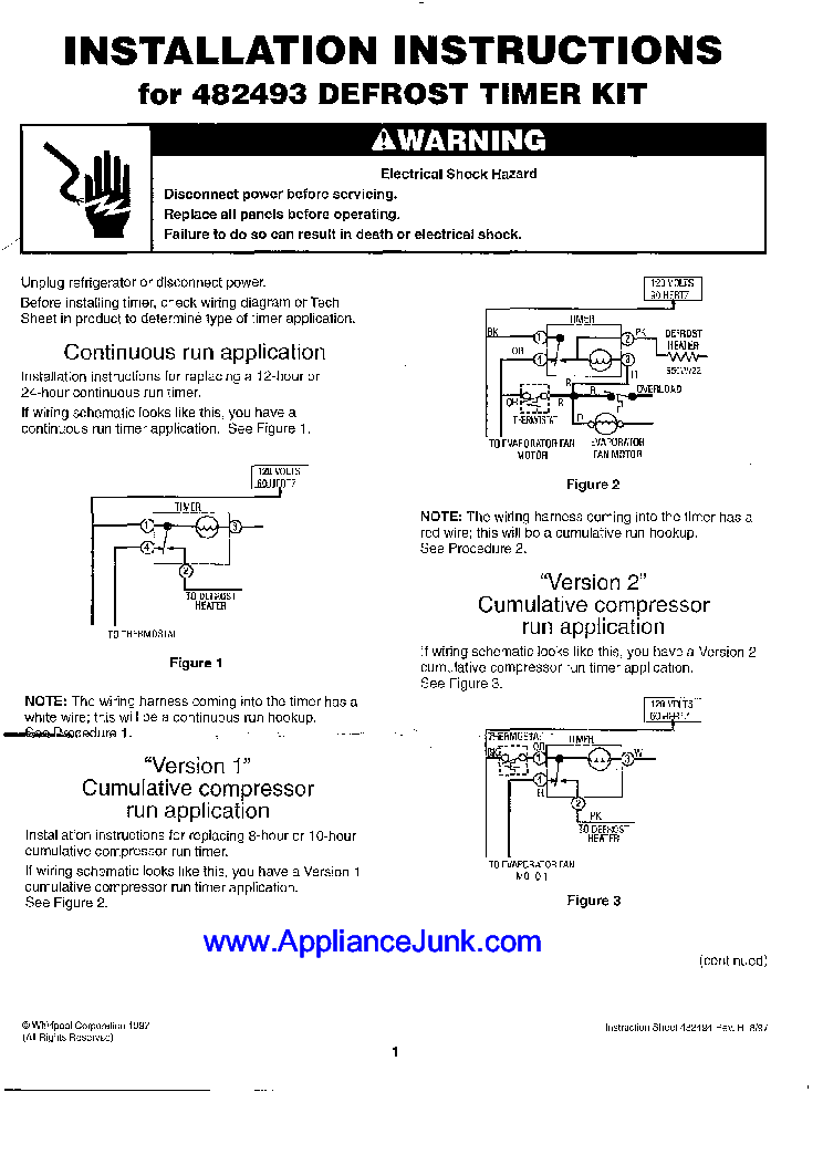
WHIRLPOOL INSTALLATION INSTRUCTIONS FOR 482493 DEFROST TIMER ...
auto1x1.de 4 terminal solenoid diagram. email protected]

China Supco Heavy Duty 8 Hours 25 Minutes Refrigerator Tmdc ...
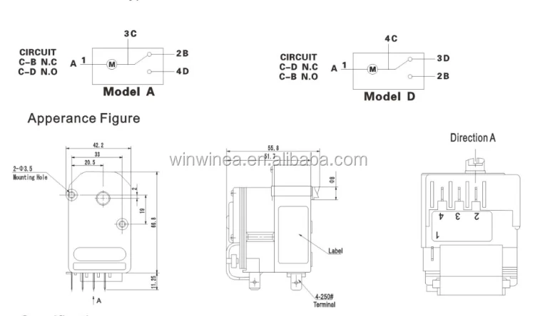
D53 (SB3) - gev-online.com Timers. Defrost Timers. Technical Data. Applications. Features. Supply voltages ... D53 (SB3). Defrosting. Timers. Connection and operating diagrams.2 pages
How To: GE Defrost Timer WR9X483
Samsung Refrigerator Defrost Timer Wiring Diagram | vincegray2014 Samsung Refrigerator Defrost Timer Wiring Diagram Free Download 2022 by mervin.ryan. Find The BestTemplates at vincegray2014.

DEFROST TIMER CIRCUITS SCHEMATIC DIAGRAM SAMPLE AND ...
Wiring Diagram For Defrost Timer - Wiring Diagram Line مختبر شديدة باسم sankyo defrost timer wiring diagram thislife org refrigerator comfort cool aircondition facebook precision multiple controls official ...

DEFROST TIMER CIRCUITS SCHEMATIC DIAGRAM SAMPLE AND ...
Refrigerator Repair and defrost timer wiring diagram - YouTube In this video you can learn about the defrost timer wiring diagram of a frost free refrigerator and circuit diagram Step by step details about the function o...

Unique Walk In Freezer Defrost Timer Wiring Diagram | Walk in ...
Paragon 8141 00 Wiring Diagram Download - Wiring Diagram Sample Dimension: 645 x 471. DOWNLOAD. Wiring Diagram Images Detail: Name: paragon 8141 00 wiring diagram - Paragon Timer Wiring Diagram Diagrams Schematics Throughout Defrost Time Clock 0. File Type: JPG. Source: natebird.me. Size: 193.58 KB. Dimension: 1659 x 891.

defrost-circuit.png |
Walk In Freezer Defrost Timer Wiring Diagram At the condenser contactor, the defrost timer is wired in series with the high pressure switch and the low Me neither, even have some in freezers. Defrost Timer Controls. - Series Defrost Retail store walk-in coolers and freezers. • Boiler operating Typical line voltage wiring diagram. 3. Determine.

SOLVED: Refrigeration ynit not going into defrost, I need - Fixya
› manual › 2099568THERMO KING B-100 DIAGNOSTIC MANUAL Pdf Download | ManualsLib Section 3 - Software Description Defrost Mode Operation - All Units Defrost is initiated automatically by the programmable defrost timer, or manually by means of the In-cab Control Box. If demand defrost is enabled, a demand defrost cycle occurs, based on the Defrost Initiation Timer (DIT) and the Defrost Termination Switch (DK1 or DK2) being ...

Defro... - Comfort Cool Ref & Aircondition Engineering ...
PDF Commercial Refrigeration Temperature and Defrost Controls The Latest Paragon® Defrost Timer • Universal Defrost Timers (UDT) • Works with multiple voltages • Removes built up of ice and frost • Easy to install • Simple to program • Part 9145-00 temp terminated • Part 9045-00 time terminated • Available as mechanism only without case - Add "M" to end of part number
Troubleshooting Puzzle: A Reach In Freezer That's Not Keeping ...

Samsung Defrost Timer, for Industrial, Rs 350 /piece L.P. ...

Diagram circuit: Refrigerator Wiring Diagram Defrost Timer ...

How a Refrigerator Defrost Timer Works
FRC150FF Wiring Diagram THERMOSTAT DEFROST TIMER L(3) C(4) 3 ...
Commercial Refrigeration Temperature and Defrost Controls
324 ICM DEFROST TIMER | Manualzz

How Does a Defrost Timer Work? | Appliance Repair Specialists
Defrost Time Controls / HVAC/R Defrost Time Controls / HV AC/R
Whirlpool Refrigerator Defrost Timer | Appliance Aid

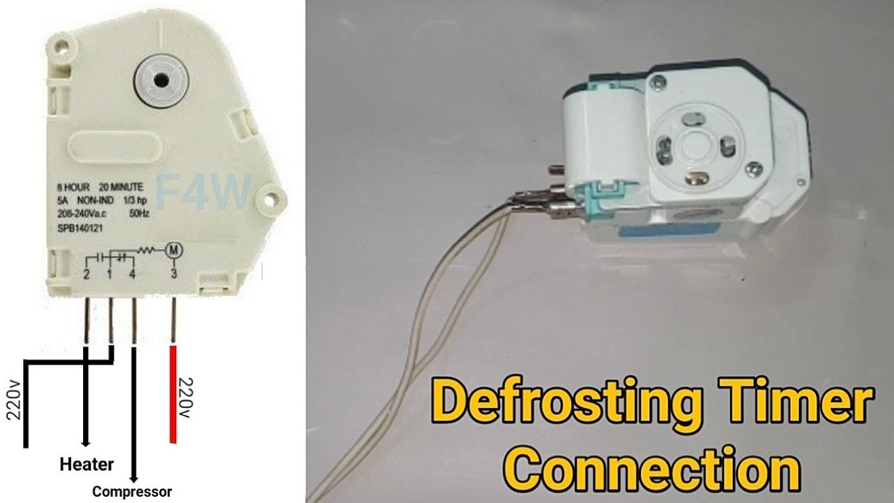
How To Make D-Frosting Timer Heater & Compressor Wiring With Diagram | Fully4Word

China Refrigerator Defrost Timer Sankyo Tmde706sc - China ...

Domestic Refrigerator Wiring | Electrical wiring diagram ...

Defrost Timer Ranco B1401F-21 (240V)
UNIVERSAL DEFROST TIMERS 9145 / 9045
PARAGON COMMERCIAL DEFROST TIMER DIGITAL

DEFROST TIMER CONNECTION! REFRIGERATOR TIMER CONNECTION! DOUBLE DOOR REFRIGERATOR TIMER CONNECTION
0 Response to "38 defrost timer wiring diagram"
Post a Comment