41 bluetooth transmitter and receiver circuit diagram
Bluetooth Transmitter - Chipset, Power, Datasheet and Uses 1) Bluetooth 5.0 2) Low power consumption 5v @60mA 3) Stereo channel 4) 2400MHz-2800MHz frequency 5) Dual mode- Receiver, transmitter 6) -80dbm Receiving sensitivity 7) 40g weight 8) Indicator led's 9) 30-meter range Ask Question Comment Step 9: Bluetooth Versions: Ask Question Step 10: JLCPCB: JLCPCB is the one of the most popular PCB makers. How to Configure HC-05 Bluetooth Module As Master and Slave ... 1. Firstly, connect the components as shown in the diagram above. From the diagram, the VCC of HC-05 is connected to the 3.3V of the Arduino Uno. If the VCC of HC-05 is connected directly to 5V of Arduino Uno, there is a high possibility that HC-05 will be damaged. But still if you insist to do so, DO IT AT YOUR OWN RISK. 2.
ESP32 Datasheet - SparkFun Electronics 5.5 Bluetooth Radio 28 5.5.1 Receiver - Basic Data Rate 28 5.5.2 Transmitter - Basic Data Rate 28 5.5.3 Receiver - Enhanced Data Rate 29 5.5.4 Transmitter - Enhanced Data Rate 29 5.6 Bluetooth LE Radio 30 5.6.1 Receiver 30 5.6.2 Transmitter 30 6 Package Information 32 7 Supported Resources 33 7.1 Related Documentation 33 7.2 Community Resources 33
Bluetooth transmitter and receiver circuit diagram
Duplex (telecommunications) - Wikipedia A duplex communication system is a point-to-point system composed of two or more connected parties or devices that can communicate with one another in both directions. Duplex systems are employed in many communications networks, either to allow for simultaneous communication in both directions between two connected parties or to provide a reverse path for the monitoring and remote adjustment ... IR Transmitter and Receiver Circuit Diagram Aug 20, 2015 · IR Transmitter Circuit Diagram. We are using TSOP1738 as IR receiver, so we need to generate the modulated IR of 38 kHz. You can use any TSOP, but you need to generate IR of respective frequency as TSOP. So we are using 555 timer in Astable mode to oscillate the IR at 38KHz frequency. As we know oscillation frequency of 555 timer is decided by ... FM Transmitter circuits with schematic diagrams This FM receiver circuit uses CXA1019 is a bipolar silicon monolithic FM/AM radio receiver IC from Sony. Transmit your telephone - This is an interesting circuit where you can transmit your telephone conversations in FM. It is a simple circuit that you can assemble with your commonly available components and 3 transistors.
Bluetooth transmitter and receiver circuit diagram. Wholesale Bluetooth Transmitter And Receiver Circuit Diagram Products ... Find wholesale Bluetooth Transmitter And Receiver Circuit Diagram manufacturers from China, India, Korea, and so on. Source good quality Bluetooth Transmitter And Receiver Circuit Diagram products for sale at factory prices from online Chinese, Indian, Korean, and other countries' manufacturing companies on Global Sources. Bluetooth Function Generator Circuit | Homemade Circuit Projects Block Diagram: The Bluetooth Function Generator Circuit: The amplifier circuit consists of a popular op-amp IC 741 and two resistors which determines gain. The resistors R1 and R2 are well selected for best performance of the function generator, altering the values may lead to inconsistent wave generation at the output. Arduino LoRa Communication - Transmitter & Receiver Setup for ... Sep 26, 2019 · Below is the hardware setup for Arduino Lora Transmitter: Receiving Side- Interfacing LoRa SX1278 with Arduino UNO. For the Receiving side, we will use an Arduino Uno with LoRa module and 16×2 LCD Display module. The circuit diagram to connect the Arduino with LoRa and LCD module is shown below How to make a bluetooth audio receiver circuit, simple audio ... - YouTube How to make a simple remote control amplifier using transistor 13003 and D882. Connect your phone to a mini homemade circuit. Make a bluetooth device at home...
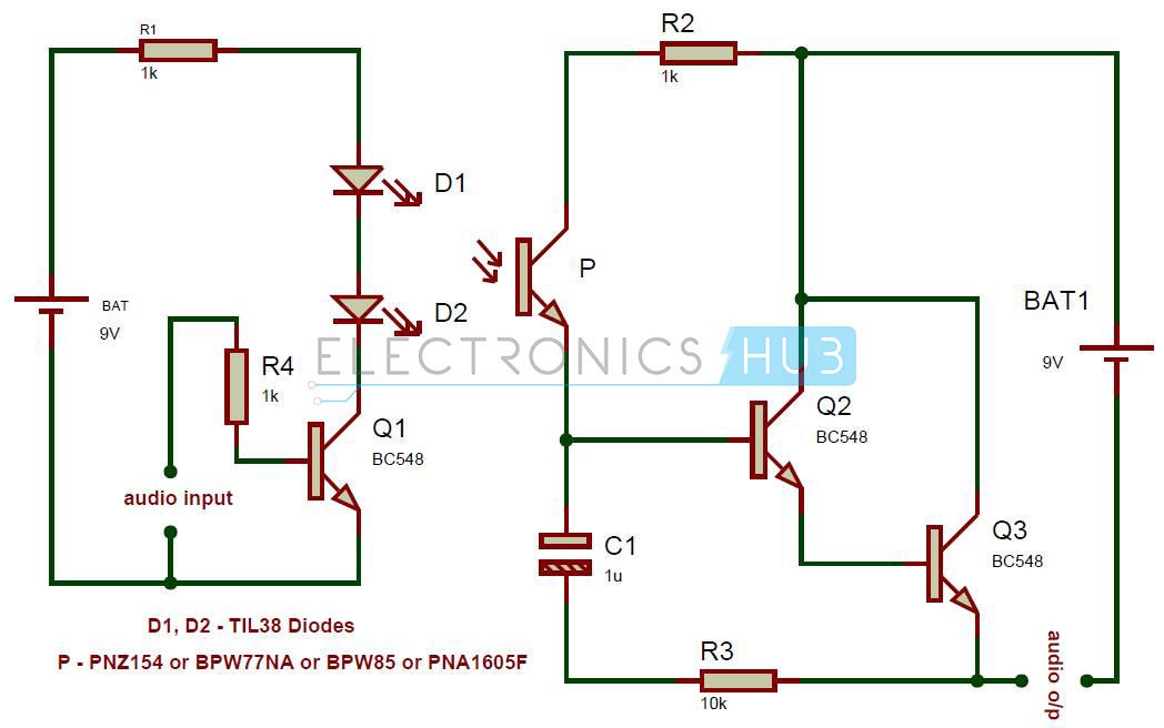
Transmitter And Receiver Circuit The receiver circuit is the most simplest ever made.It is making use of radio diode rather than any inductor.We are not using any tuning circuit here.The ic used here is a high gain Lm356 amplifier which picks up signals from the 1n34 radio receiver diode and amplifies it to a certain level. Radio Transmitter and Receiver | Working | Block Diagram A block diagram of a simple continuous wave (CW) transmitter is shown in Figure 6. The first block is the conventional crystal oscillator and then the final power amplifier. A power supply is provided for the oscillator and the final power amplifier. Figure 6. A block diagram representing various stages of a basic continuous wave radio transmitter. Bluetooth Transmitter Receiver Circuit Diagram [PDF] - kelliemay now is bluetooth transmitter receiver circuit diagram below. Guide to Wireless Communications Jorge Olenewa 2013-01-01 GUIDE TO WIRELESS COMMUNICATIONS, 3rd Edition is designed for an entry level course in wireless data communications. The text covers the fundamentals wireless communications and provides an overview of protocols, transmission ... PDF Bluetooth Audio Transmitter Receiver Circuit Diagram IR Transmitter and Receiver Circuit Diagram. ESP32 â€" Cheapest IoT WiFi and Bluetooth ready module. Radio Frequency RF Remote control circuit Gadgetronicx. Bluetooth Technology 101 Tom s Hardware. Object Detecting Android Mobile Phone Controlled Bluetooth. Electronic Circuits and Diagrams Electronic Projects and. Electronic Circuit ...
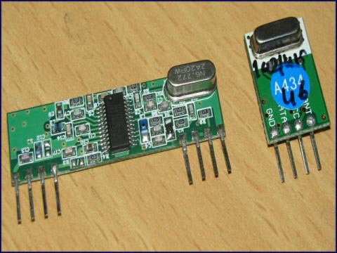
RF Transmitter and Receiver Circuit Diagram The Transmitter module consists of three pins namely Vcc, Din and ground as shown above. The Vcc pin has a wide range input voltage from 3V to 12V. The transmitter consumes a minimum current of 9mA and can go as high as 40mA during transmission. The center pin is the data pin to with the signal to be transmitted is sent. Bluetooth Circuit- Everything you need to know about Bluetooth transmitter circuit plays a vital role in this process. It contains three essential components- regulated voltage, wireless communication, and sensor data. The first component allows delivering power and strength to the detector circuit and the microcontroller. It merely works all the electrical functions of the Bluetooth device. IR Transmitter and Receiver - Circuits DIY Here, in this circuit, we are utilizing TSOP1738 as a signal receiver, its operation will be discussed here in detail. So, we have to create a modulated Infrared beam of approximately 38 kHz. You can likewise use any TSOP, yet you have to produce an IR beam of respective frequency as TSOP. Henceforth, to do this operation, we utilize 555 timer IC. Basics of UART Communication - Circuit Basics Apr 05, 2020 · UART stands for Universal Asynchronous Receiver/Transmitter. It’s not a communication protocol like SPI and I2C, but a physical circuit in a microcontroller, or a stand-alone IC. A UART’s main purpose is to transmit and receive serial data. One of the best things about UART is that it only uses two wires to transmit data between devices.
Simulink block diagram of Bluetooth transmitter and receiver ...
Wireless Battery Voltage Monitoring using Arduino, NRF24L01, & Bluetooth Wireless Battery Monitoring, Transmitter Circuit Diagram: This is the transmitter side circuit diagram. The VCC and GND pins of the NRF24L01 module are connected with the Arduino's 3.3V and GND pins. ... Next I added the Bluetooth Module and with this our receiver circuit is completed. Next we are going to connect the Voltage Sensor with the ...

Wireless Mobile Charger Circuit Diagram - Engineering Projects
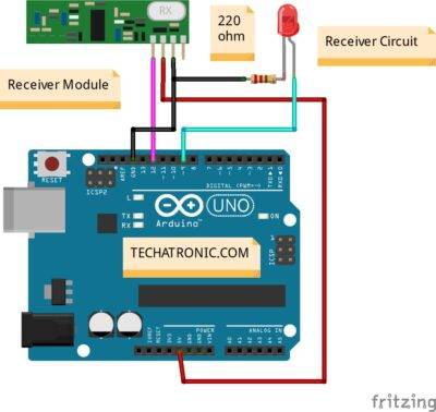
Smart Blind Stick using Arduino - Circuit Digest Jan 08, 2018 · The other is a small remote RF transmitter circuit which will be used to locate the main circuit. The main board’s circuit diagram to build a blind stick using ultrasonic sensor is shown below: As we can see an Arduino Nano is used to control all the sensors, but you can also build this Smart blind stick using arduino uno but following the ...
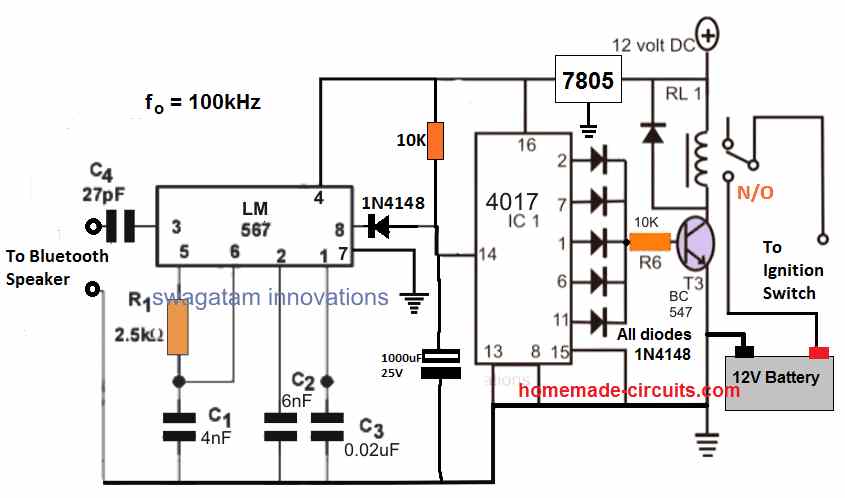
Bluetooth Car Ignition Lock Circuit - Keyless Car Protection ...
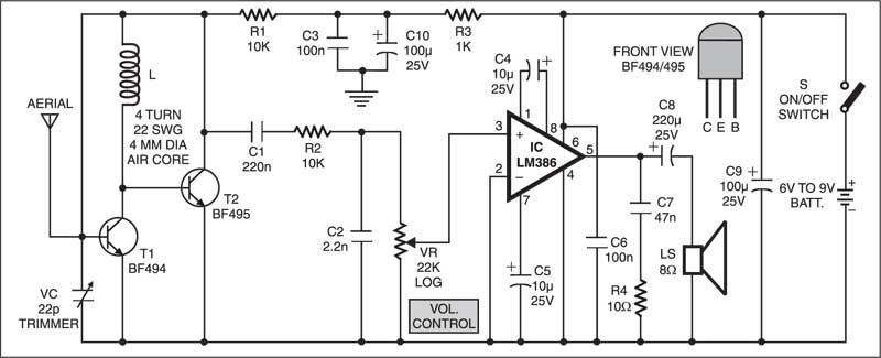
Electronics Hub - Tech Reviews | Guides & How-to | Latest Trends Initially give transmitter and receiver the connections separately as per the circuit diagram Apply power to the both transmitter and receiver sections using two 9V batteries. Connect an 8 Ω speaker at the output of LM386 Audio Amplifier IC. Make sure that distance between Transmitter and receiver sections is below 30cm.
IR-based Wireless Audio Transmitter and Receiver
Bluetooth Technology - Electronic Circuits and Diagrams-Electronic ... Piconets actually refer to the process called Personal Area Network (PAN), in which a network is created between all the devices which have Bluetooth facility with the range of transmission and reception. This method is started automatically by the devices and does not need a command from the user.

555 IC Wireless Audio Transmitter and Receiver
5 Bluetooth Circuit Basics Every Beginner Needs to Know Bluetooth transmitter circuit board To be able to share files wirelessly, whether they are JMPEG or MP3, you must have a Bluetooth transmitter circuit board. Its basic function is to transfer certain files from one device to another. This board consists of wireless transmission, a regulated voltage and a sensor.
Wireless Switch using 434MHz ASK Modules
Wireless Headphones Transmitter Circuit - ElectroSchematics.com This wireless headphones transmitter assures a quality reception over 2 meters. The oscillator frequency is between 1750KHz and 3500KHz and for antenna we use a ferrite bar. IC1 amplifies the audio signal and TC1 is a buffer. D1 signals that the transmitter is on and is a voltage stabilizer for the oscillator .
Wireless RF Module | RF Transmitter and Receiver | Latest ...
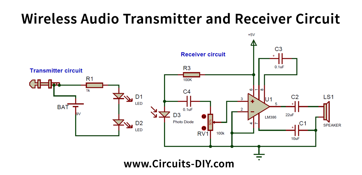
IR based Wireless Audio Transmitter and Receiver Circuit The principle behind the circuit is that, we will have two individual circuits. One is the transmitter circuit and the other is the receiver circuit, the transmitter circuit will be connected to the 3.5mm Audio jack for audio input and the receiver circuit will be connect to a speaker to play the songs.
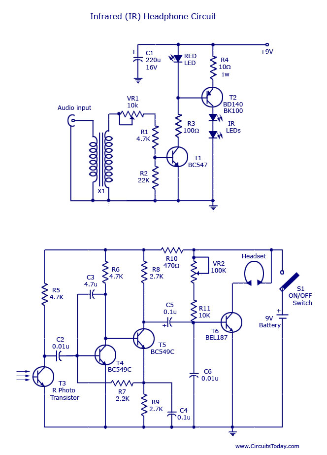
IR Headset Circuit with headphone Transmitter and Receiver ...
Simple AM Receiver Circuit The schematic that appeared above is a basic AM receiver circuit. It utilizes just a single transistor and a few other small electronic components. In the respective circuit, the coil and 365pF variable capacitor structure the main circuit. Which gets the signals through the antenna which acts as a receiving wire.

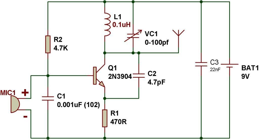
Wireless microphone schematic
Bluetooth Transmitter and Receiver Circuit Diagram - DocsLib Bluetooth Transmitter And Receiver Circuit Diagram G0mrf 29 45 Mhz. The bluetooth communication interface, and bluetooth transmitter circuit of equipment which has occurred in a wireless signals, low impedance load to detect and can use relay modules. TNC Digi Trackernow with USB Bluetooth and interior altitude GPS receiver.

IR Transmitter and Receiver Circuit Diagram
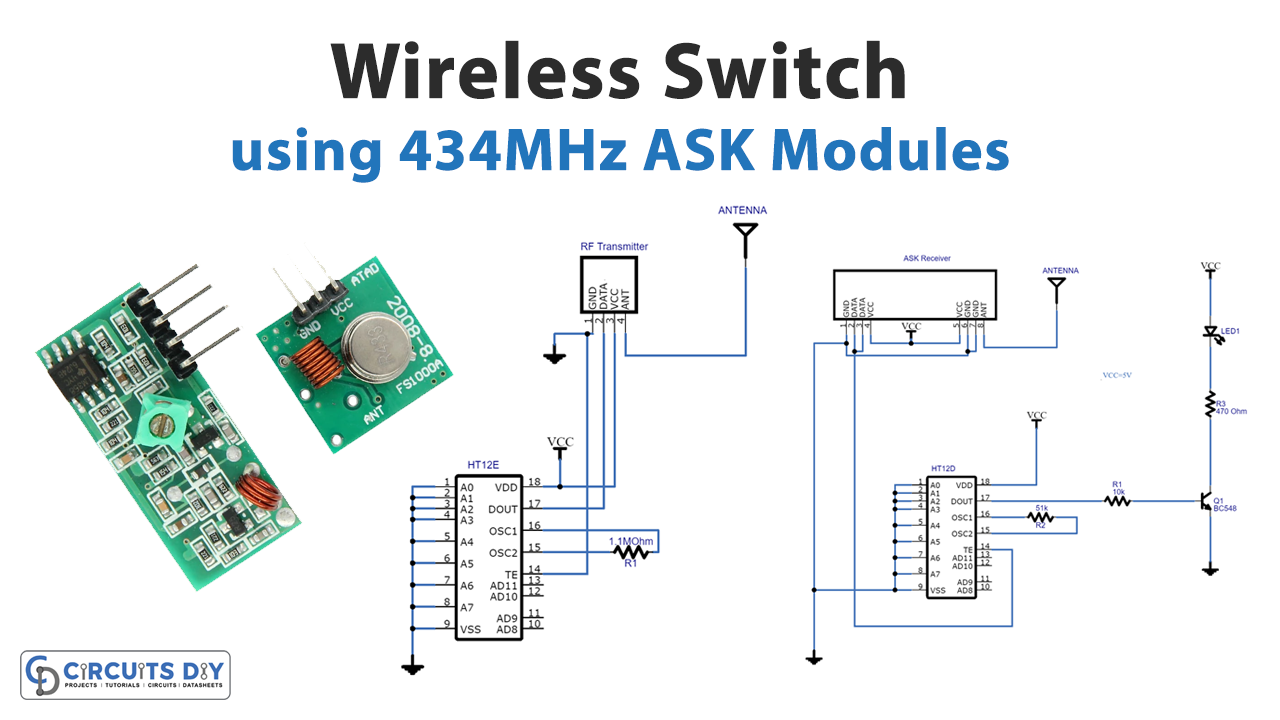
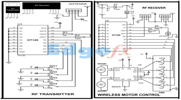
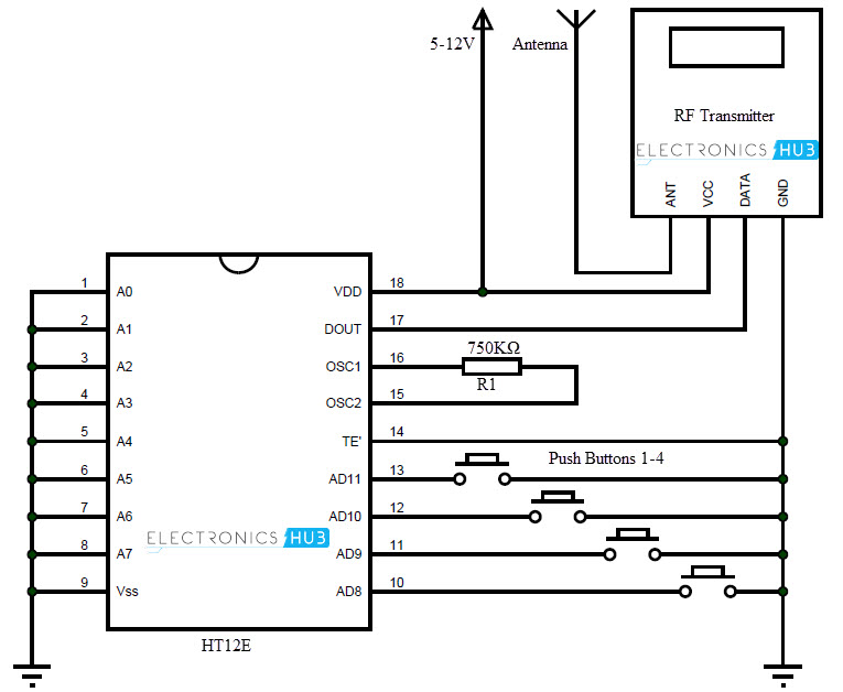
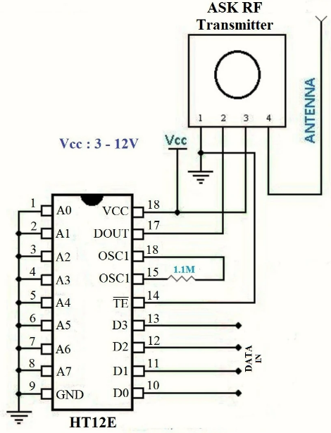
RF Transmitter and Receiver Circuit using RF Module Circuit Diagram of RF Receiver 433MHz RF Receiver Circuit Diagram Circuit Description Transmitter Circuit The HT12E encoder IC VSS pin is connected to the power supply Ground (-) and the VDD is connected to the power supply VCC (+). IC A0 - A7 pins (pin 1 - 8) are connected to the Ground (-) to set the address at 0b00000000.
Wireless RF Module | RF Transmitter and Receiver | Latest ...
Wireless Mobile Charger Circuit Diagram - Engineering Projects Receiver Circuit for Wireless Mobile Charger Circuit Diagram: - Receiver circuit shown in figure 2 is built around LC tuned circuit (L 2 with C 7 and C 8 ), a current regulator (buck and boost) IC MC34063, Schottky diode (1N5819), and a few passive components. The transmitted oscillation magnetic field is detected by L-C tuned build around ...
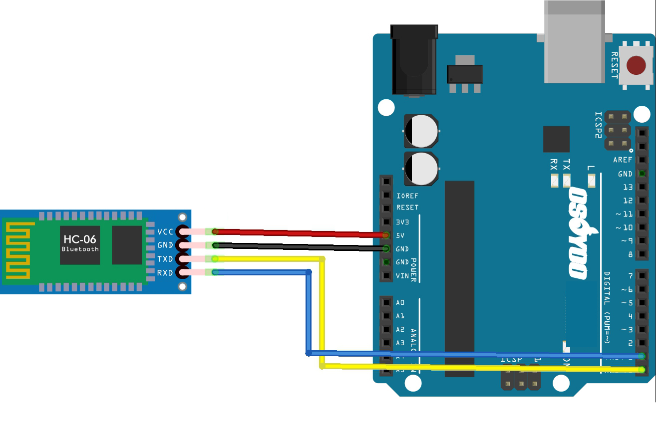
HC06 Bluetooth transmitter/receiver sensor « osoyoo.com
Making a Wireless Doorbell Circuit | Homemade Circuit Projects The Wireless Doorbell transmitter and receiver circuit are incorporated below: All Transistors are 2N3563, the U shape coil is a single half turn using a 1mm copper wire with 5mm diameter The most fundamental constituent is the transistor.
Wireless Transmitter and Receiver using RF Modules
How to Make a Walkie Talkie Circuit - DIY Electronics Projects Transmitter Circuit Diagram. Transmitter Circuit Explanation. Different voice modes. The Receiver. How to use this Walkie talkie. The Idea: This project utilizes FM radio as receiver and FM transmitter to send voice. A person who wants to communicate with the other will have a set of FM radio and FM transmitter and same with the other person.
EEEShopBD Bluetooth 4.0 Audio Receiver Template buy in bd
Wireless Alarm Transmitter and Receiver Schematic Circuit Diagram Wireless Alarm Transmitter and Receiver Schematic Circuit Diagram. Wise Tech October 18, 2018. 0 215 3 minutes read. Here are two circuits that make it possible to add up to eight detectors to an existing alarm system without running a single cable. Each transmitter has a unique number that is reported to the central unit in the event of an ...
Proyek Audio Bluetooth Transmitter / Sender dengan ESP32 dan ...
How to Design a Bluetooth Low Energy Circuit with Sensor Technology Tutorial on designing a Bluetooth Low Energy (BLE) circuit with the ability to measure 9-axis motion, humidity, and temperature. Tutorial on designing a Bluetooth Low Energy (aka Bluetooth Smart) circuit with the ability to measure 9-axis motion, humidity, and temperature.

Bluetooth transmitter circuit and schematics | Bluetooth ...
Build A Simple Wireless Bluetooth Stereo Audio System For The Outdoors This design uses a Nokia BH-214 Bluetooth stereo headset. It has the 3.5-mm audio connector, making it very easy to take audio signals from a headset's printed-circuit board (PCB) and feed ...

Bluetooth Transmitter – Chipset, Power, Datasheet and Uses ...
Build Your Own Bluetooth Audio Receiver : 6 Steps - Instructables Step 1: Tools We Need: 1-Bluetooth speaker 2-cutter 3-screw driver 5-Solder iron 6-wire 7-tin Add Tip Ask Question Comment Download Step 2: Disarm the Speaker:
Password Protected Bluetooth Based Remote Control Project
Bluetooth Circuits - Circuit Board Fabrication and PCB ... - WellPCB The Bluetooth Circuits Process ① The Pre-production Step ② Inner Layer Imaging ③ Inner Layer Etching ④ Inner Layer AOI We use the data (Gerber file) that you send us to create the production information for your customized boards. Our experts match your specifications with the capacities for compliance purposes. ⑤ Lamination ⑥ PCB Drilling

USB FM Transmitter Circuit
FM Transmitter circuits with schematic diagrams This FM receiver circuit uses CXA1019 is a bipolar silicon monolithic FM/AM radio receiver IC from Sony. Transmit your telephone - This is an interesting circuit where you can transmit your telephone conversations in FM. It is a simple circuit that you can assemble with your commonly available components and 3 transistors.
RF Transmitter and Receiver Circuit Diagram
IR Transmitter and Receiver Circuit Diagram Aug 20, 2015 · IR Transmitter Circuit Diagram. We are using TSOP1738 as IR receiver, so we need to generate the modulated IR of 38 kHz. You can use any TSOP, but you need to generate IR of respective frequency as TSOP. So we are using 555 timer in Astable mode to oscillate the IR at 38KHz frequency. As we know oscillation frequency of 555 timer is decided by ...

FM Transmitter Circuits
Duplex (telecommunications) - Wikipedia A duplex communication system is a point-to-point system composed of two or more connected parties or devices that can communicate with one another in both directions. Duplex systems are employed in many communications networks, either to allow for simultaneous communication in both directions between two connected parties or to provide a reverse path for the monitoring and remote adjustment ...
RF(433MHz, 418MHz, 315MHz) Module Transmitter/Receiver Pair ...
How to make an FM transmitter - BuildCircuit.COM
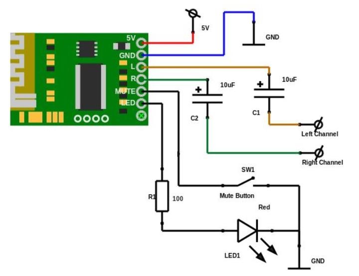
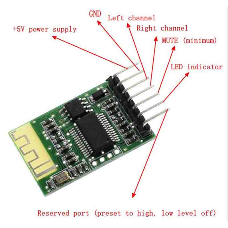
Bluetooth Audio Receiver Module - Stereo Output - 5V DC Operation
What is RF Transmitter and Receiver: Applications All Details ...
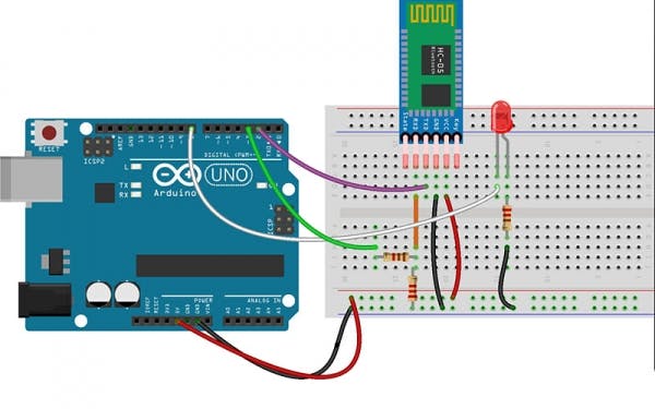
Getting Started with HC-05 Bluetooth Module & Arduino ...

Simple IR Audio Transmitter and Receiver Circuit
Simple IR Audio Transmitter and Receiver Circuit
Wireless Transmitter and Receiver using ASK RF Module
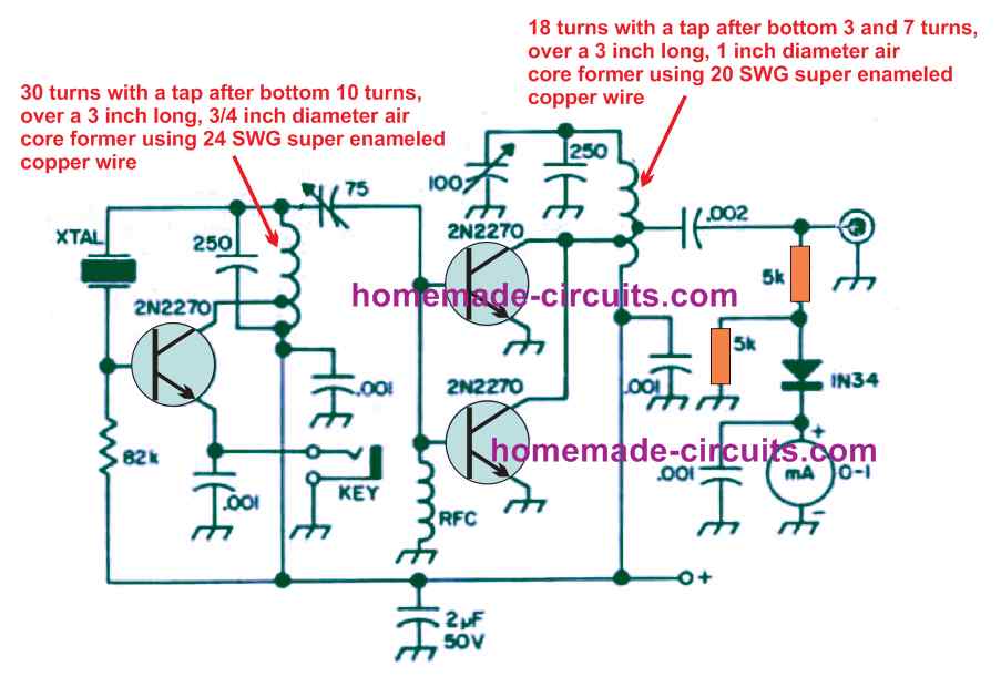
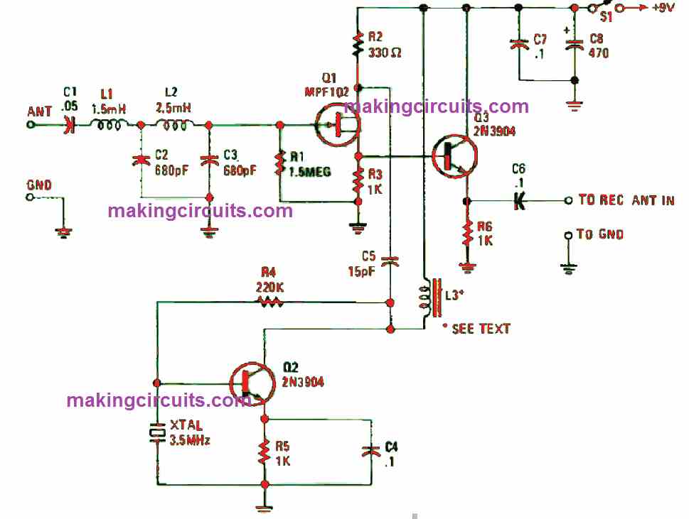
Transmitter Receiver Circuit for 80-meter Ham Radio ...
Designing FM Receiver Circuit | Complete Circuit Explanation

DIY Bluetooth Audio Adapter - BluFi : 9 Steps (with Pictures ...
Basic Model of RF Transmitter and Receiver (Part 1/23)

Wireless Transmitter and Receiver using RF Modules
Very Low Frequency (VLF) Converter Circuit

Circuit diagram illustrating the ultrasonic transmitter and ...

IR transmitter and receiver circuits | Electronic schematics ...

Teardown Tuesday: Bluetooth Car FM Radio Transmitter - News

Bluetooth Transmitter / Receiver
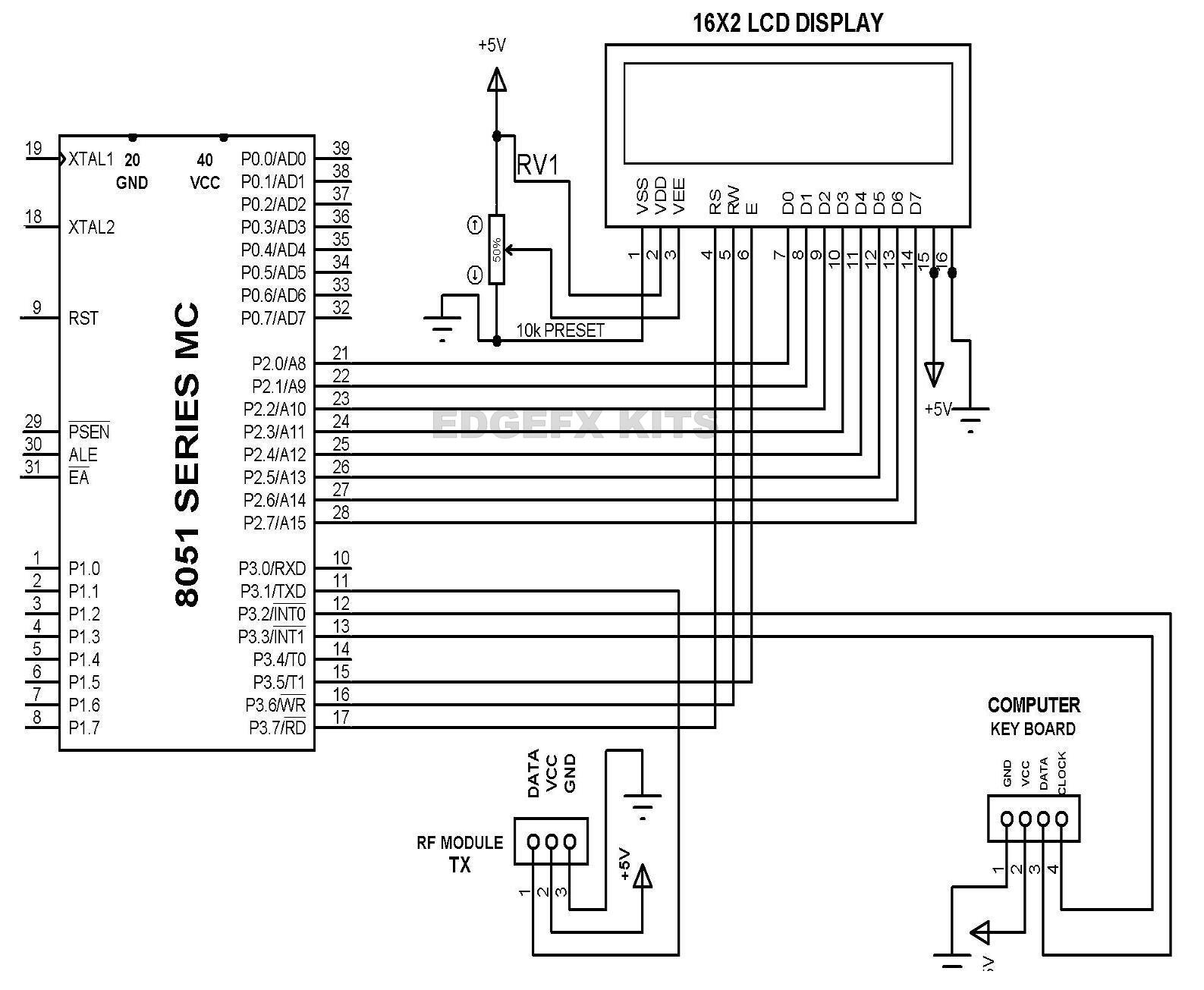
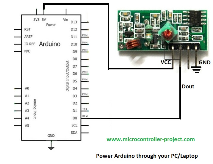
Arduino with Rf module Interfacing | Rf module with Arduino

RF Transmitter and Receiver Circuit Diagram
0 Response to "41 bluetooth transmitter and receiver circuit diagram"
Post a Comment