40 accelerator pedal position sensor wiring diagram
APP Sensor Interactive Wiring Diagram - YouTube APP Sensor Interactive Wiring Diagram 13,090 views Jul 18, 2018 APP Sensor Interactive using the Wiring Diagram System. Here we'll cover operation and some testing of the APP or... bmw e46 accelerator pedal wiring diagram schematic e46 wiring need. 6 Pin Throttle Position Sensor Wiring Diagram | Wiring Expert Group wiring-expert.blogspot.com. What's Going On In My Shop Currently... - Page 4 - E46Fanatics forum.e46fanatics.com. Pin By Andrea Paraggio On Docs | Bmw E46, Diagram, Electrical Wiring . Accelerator Pedal Module ...
Accelerator Pedal Position Sensors - Autosphere The two main sources of input data are the accelerator pedal position sensors (APP1 and APP2) and throttle position sensors (TPS). ... as illustrated in the wiring diagram in Figure 2. Figure 2 (Photo: ALLDATA) ... Older Acuras and Hondas employ a throttle valve cable mounted between the accelerator pedal and APP sensor, which, in turn, sends ...
Accelerator pedal position sensor wiring diagram
⚡ Throttle Position Sensor Wiring Diagram ⭐⭐⭐⭐⭐ ⚡ Throttle Position Sensor Wiring Diagram ⭐⭐⭐⭐⭐ by. KR on. September 15, 2022 ... Accelerator Pedal Position Sensor 🏎️ How To Diagnose And Fix? 6 Pin Accelerator Pedal Position Sensor Wiring Diagram As we covered the basics of the accelerator pedal position sensor and learned what this sensor does behind the curtain. We can now focus more on the technical aspect of this sensor. Namely, the 6-pin accelerator pedal position sensor wiring diagram. How this sensor is wired? GM Electronic Throttle Body Circuit Descriptions And Testing Tips And Accelerator Pedal Assembly. In this section, we'll focus on the Electronic Throttle Body. As you have probably already observed, there are 8 wires sticking out of the Electronic Throttle Body. When looking down at the Electronic Throttle Body's connector, the top row (from left to right) has 4 wires which are labeled from A to D (see photo).
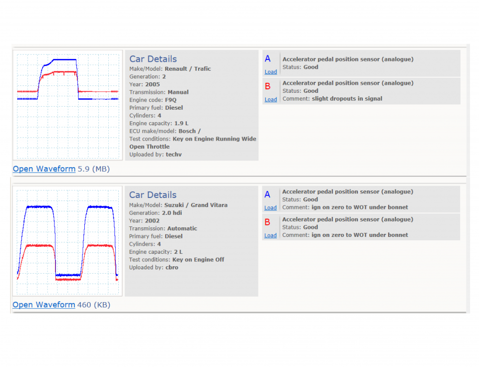
Accelerator pedal position sensor wiring diagram. Signs of a Bad Accelerator Pedal Position Sensor ... - Rx Mechanic A driver determines the rate of a car's speed by continually depressing the accelerator pedal, which signals the throttle body to allow the more air-fuel mixture to go in. The "throttle position sensor" and the APP sensor monitor the throttle body valve positioning and signals to the ECU. Then, the ECU works with that signal to determine ... Wiring diagram for accelerator pedal to ECU The cranks sensor should be a 2 pin inductive sensor that generates a voltage when the engine spins. The cam sensor is a hall effect sensor and will have a voltage from the ecu @ 5v like you say. If you are measuring 2.3v, on a 3 wire sensors supply wire then there is either a wiring fault or an ecu fault. Nissan Accelerator Pedal Position (APP) Sensor - Erwin Salarda WIRING DIAGRAM : Nissan accelerator pedal position (APP) sensor Wiring Diagram WIRING TECHNICAL DATA: Nissan accelerator pedal position (APP) sensor WIRING TECHNICAL DATA TECHNICAL SPECIFICATION: Nissan accelerator pedal position (APP) sensor TECHNICAL SPECIFICATION Accelerator Pedal Released Position Learning DESCRIPTION Accelerator pedal position sensor - analog - Pico auto The two most common methods of signal generation are as follows: Figure 2: Potentiometer 1 generates a signal of 0.3 to 4.8 volts (red trace in Figure 2) and potentiometer 2 generates a signal of 0.5 to 4.8 volts (blue trace in Figure 2 ). With an accelerator pedal position of 45 degrees, potentiometer 1 may be outputting a signal of 2 volts ...
Gm Accelerator Pedal Position Sensor Wiring Diagram accelerator pedal position sensor wiring diagram wiring diagram is a simplified satisfactory pictorial representation of an electrical circuit it shows the components of the circuit as simplified shapes and the skill and signal links amongst the devices. 6 = pedal sensor 2 (tc pin 25 & ecu pin ana1 input) pedal sensor pedal sensor bosch 021 907 … williams controls accelerator pedal wiring diagram Accelerator pedal position sensor. 13 Images about Accelerator pedal position sensor : Williams Controls Accelerator Pedal Wiring, LS2 throttle body harness adapters - PerformanceTrucks.net Forums and also LS2 throttle body harness adapters - PerformanceTrucks.net Forums. accelerator pedal position sensor wiring diagram - Wiring Diagram subaru legacy service manual dtc chevrolet throttle position sensor bosch dbw body and pedal wiring diagram p2122 08482 vw accelerator og 8pin tps module color wire forklift circuit control system need help with a connector main nissan almera tino v10 instruction printer friendly view dodge caliber part 1017 i have p2127 code ecm diagrams to … 6 pin accelerator pedal position sensor wiring diagram - Lace Kit So, a 6 pin accelerator pedal position sensor wiring diagram is, two wires are for the earth, two for the input voltage, and two for signals back to the computer (ecu). 6 pin throttle position sensor wiring diagram (drive by wire throttle) motor positive motor negative signal wire (sensor 1) signal wire (sensor 2) hot power wire.
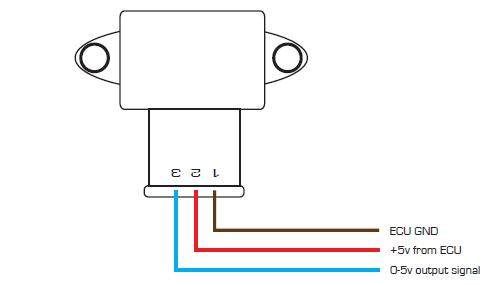
3, 4, 5, 6, & 8 Wire Throttle Position Sensor Wiring Diagram Here is the wiring diagram of the cable-operated throttle body. Signal Wire (Sensor 1) Hot Power Wire (5 Volt Reference voltage comes from the ECU) Earth Wire Signal Wire (Sensor 2) Hot Power Wire (5 Volt Reference voltage comes from the ECU) Earth Wire A cable-operated six-pin throttle position sensor has two potentiometers (sensors). Accelerator Pedal Position Sensor, 6 Pin Wiring Diagram, & Types Some accelerator pedal position sensors (APPS) have two or three potentiometers inside the APPS sensor with individual wiring. A potentiometer consists of three wires, earth, voltage, and a signal wire (wiper), which moves against the resistor to send back the voltage signal to the computer. A dual-contact type potentiometer APPS has six wires. Drive By Wire Throttle Wiring - Haltech Support Center Drive by wire technology is supported by the Elite 2500 ECU's and requires wiring of an Electronic Throttle and Accelerator Pedal Position sensor. Wiring setup and connection allocation can be found within the function in the setup page. This wiring connection allocation below is recommended as a standard practice but can be changed if required ... How To Test The GM Accelerator Pedal Position (APP) Sensor 1 The Accelerator Pedal Position sensor is inside the Accelerator Pedal Assembly. The Accelerator Pedal Assembly is not connected to the throttle plate via a cable (like in the good ole' days). That the Accelerator Pedal Assembly is made up of 3 individual position sensors. Each one has separate signal, Ground, and 5.0 volt reference circuits.
Throttle Body Wiring | Toyota Nation Forum
6 Signs Of A Bad Accelerator Pedal Sensor [Replacement Cost] The accelerator pedal position sensor is located inside the accelerator pedal. In some cases, it is possible to replace just the sensor - but on other car models, you have to replace the whole accelerator pedal. Removing the accelerator pedal can sometimes be challenging, but it is pretty straightforward on most car models.

Pic Request: Throttle Position Sensor Connector Wiring ...
THROTTLE POSITION SENSOR explanation for wiring diagram ... - YouTube THROTTLE POSITION SENSOR explanation for wiring diagram, troubleshooting and simplify tutorial - YouTube 0:00 / 13:04 THROTTLE POSITION SENSOR explanation for wiring diagram,...

Throttle Position Sensor - Toyota Engine Control Systems ...
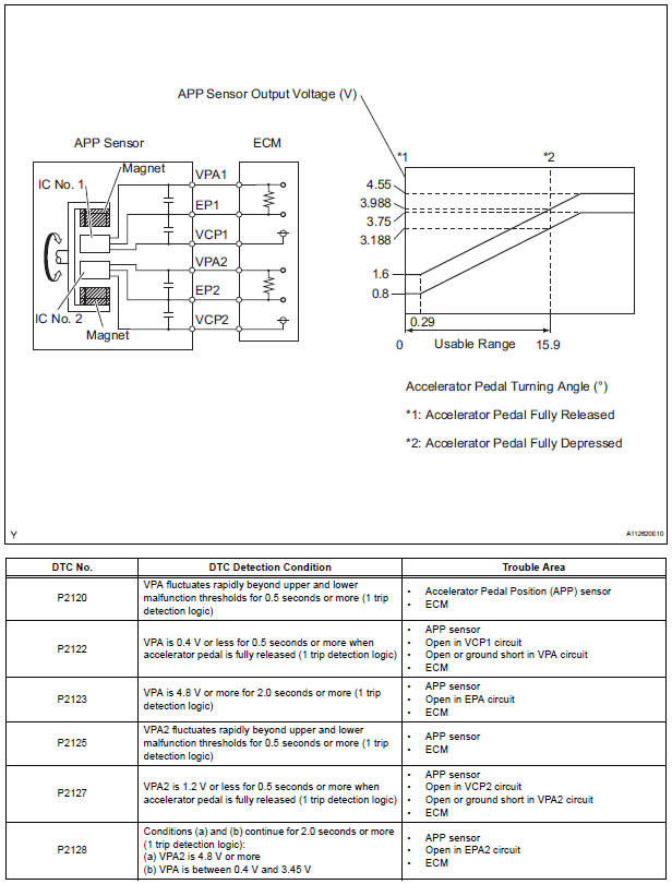
P2138 Code: Throttle/Pedal Position Sensor/Switch D/E Voltage ... Diagnostic trouble code (DTC) P2138 stands for "Throttle/Pedal Position Sensor/Switch D/E Voltage Correlation." It is triggered when the vehicle's engine control module (ECM) or powertrain control module (PCM) detects that the signals from the two throttle position sensors (or two accelerator pedal position sensors) do not correlate.

Throttle Position Sensor Testing and Explanation
adjustable pedals ford wiring diagram Accelerator Pedal Position Sensor Wiring Diagram Di 2020 . e350 toyota rzr tankbig kenwood wiringg diagrams headlight easywiring ambrasta diyparty99. 2003 Ford Expedition Fuel Pump Wiring Diagram wiringdiagramsx.blogspot.com. f150 expedition imageservice lariat nbu. 55 2006 Ford Focus Wiring Diagram - Wiring Diagram Harness

Where do the pedal wires go? Gen IV - The 1947 - Present ...
Accelerator Pedal Position Sensor | Dodge Cummins Diesel Forum Once you find that wire, read the voltage as the pedal is depressed, if the voltage spikes or falls off rather than make a smooth rise and fall, the sensor is bad. '01 dually QC 6-spd 4x4 / K&N CAI / Banks High-Ram / TunnelRam / Stainless Ex. Man. / Hamilton Street 188/220 Cam / 110# springs / ARP Studs / TST PowerMaxComp / 5" straight / triple ...
wiring harness for automobile
6 Pin Accelerator Pedal Position Sensor Wiring Diagram For Your Needs 6 Pin Accelerator Pedal Position Sensor Wiring Diagram For Your Needs. Electrical electrical wiring is a potentially hazardous task if carried out improperly. One ought to never attempt operating on electrical wiring without knowing the below tips and tricks followed simply by even the many experienced electrician.
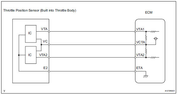
Toyota RAV4 Service Manual: Throttle / pedal position sensor ...
Accelerator Pedal Position Sensor | The Diesel Stop The Accelerator Pedal Position sensor has two potentiometers that act to validate pedal position. But if there is a problem with one sensor the pedal should still work but you will have warning indicators on. If both are malfunctioning nothing will happen with the pedal.
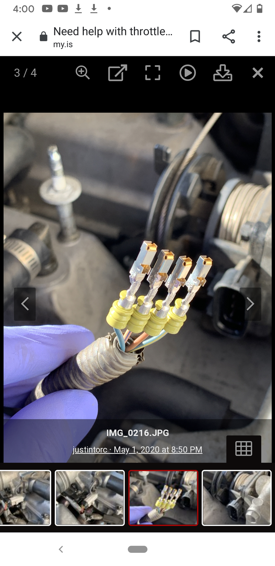
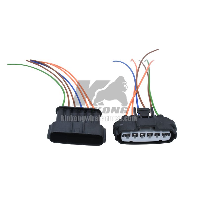
Need help with a connector wiring. | Lexus IS Forum
Accelerator Pedal Position Sensors (APPS) - Premier Auto Trade When the APPS signal/s are incorrect, the Electronic Throttle system will convert to default mode - causing: Check engine light on and fault code logged. Examples - P0121 Accel Pedal Sensor 1 Circuit performance / P1125 Accel Pedal Sensor. The throttle valve may be held in the default position, limiting engine RPM and road speed to a minimum.
2015 F-150 - Acceleration Pedal Position Wiring diagram ...
pedal assist sensor wiring diagram Pedal positio sensor wiring - General Electronics - Arduino Forum. 16 Pictures about Pedal positio sensor wiring - General Electronics - Arduino Forum : Gearbox sensors wiring diagram | For E Bodies Only Mopar Forum, Accelerator Pedal Position Sensor Wiring Diagram - Drivenheisenberg and also LH Rear Drum Brake Backing Plate 93-99 VW Jetta Golf Cabrio MK3 - Genuine.
Toyota Sienna Service Manual: Throttle / Pedal Position ...
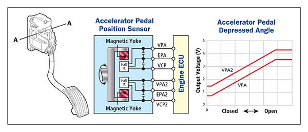
Accelerator pedal sensor - function & design | HELLA Ignition on, press pedal, then release pedal. The signal rises and falls depending on the speed at which the pedal is pressed and released. Signal recording from pin C10 SIGNAL RECORDING FROM PIN C10 Ignition on, press pedal, then release pedal. The signal rises and falls depending on the speed at which the pedal is pressed and released.

370Z Pedal Position Sensor pinout - G4+ - Link Engine ...
Bmw E46 Accelerator Pedal Wiring Diagram Basics Of Engine Throttle Position Sensors E Throttle Accelerator Pedal Module Jimmyo How Do You Know If A Throttle Position Sensor Is Bad Axleaddict Bmw E46 3 Series Manual Accelerator Throttle Electric Pedal Wiring Plug Bracket 43 99 Picclick Uk Bimmerforums The Ultimate Bmw Forum Understanding The Efi Process Page 6 Of 7 Motoiq
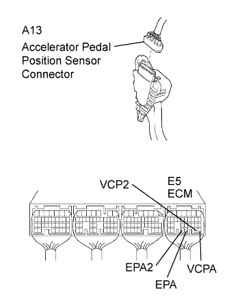
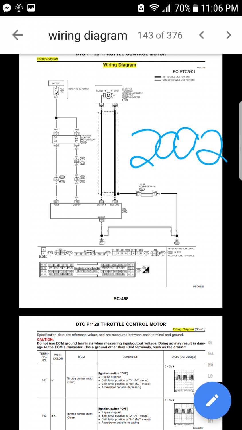
GSIC - Global Service Information Center
GM Electronic Throttle Body Circuit Descriptions And Testing Tips And Accelerator Pedal Assembly. In this section, we'll focus on the Electronic Throttle Body. As you have probably already observed, there are 8 wires sticking out of the Electronic Throttle Body. When looking down at the Electronic Throttle Body's connector, the top row (from left to right) has 4 wires which are labeled from A to D (see photo).

Accelerator pedal position sensor wiring diagram working ...
Accelerator Pedal Position Sensor 🏎️ How To Diagnose And Fix? 6 Pin Accelerator Pedal Position Sensor Wiring Diagram As we covered the basics of the accelerator pedal position sensor and learned what this sensor does behind the curtain. We can now focus more on the technical aspect of this sensor. Namely, the 6-pin accelerator pedal position sensor wiring diagram. How this sensor is wired?

Automotives HuB - App sensor wiring diagram | Facebook
⚡ Throttle Position Sensor Wiring Diagram ⭐⭐⭐⭐⭐ ⚡ Throttle Position Sensor Wiring Diagram ⭐⭐⭐⭐⭐ by. KR on. September 15, 2022 ...

FOR THE WIRING DIAGRAM THROTTLE POSITION SENSOR PLUG, IT USE ...
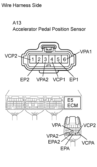
GSIC - Global Service Information Center
FWD VQ35 HR Swap TPS Sensor Wiring 5.7 Gen
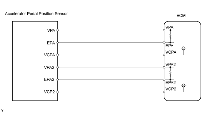
GSIC - Global Service Information Center
Drive By Wire Throttle Wiring

Throttle Body wiring diagram - Engine Maintenance and ...

p2123-accelerator pedal position sensor 1 circuit high
APP Sensor Interactive Wiring Diagram - YouTube
GSIC - Global Service Information Center

Throttle position control system | Download Scientific Diagram

GM Gen III LS PCM/ECM: Electronic Throttle Equipment Guide

Throttle Position Sensor - Toyota Engine Control Systems
Throttle Body Position Sensor Wiring Diagram Needed
TPS wiring/pinout help | Lancer Register Forum

Bimmerforums - The Ultimate BMW Forum

Wiring diagram of a forklift accelerator pedal circuit ...

Chevrolet Throttle Position Sensor Diagnosis and Repair Help ...
GSIC - Global Service Information Center

TechDoc
Accelerator Pedal Position Sensors (APPS)

APP Sensor Interactive Wiring Diagram - YouTube

370Z Pedal Position Sensor pinout - G4+ - Link Engine ...

Throttle position sensor wiring diagram. 08 int prostar isx ...
2010 Toyota Yaris ACCELERATOR PEDAL WIRING HELP - Automotive ...
Accelerator pedal position sensor - analog
Throttle position sensors
0 Response to "40 accelerator pedal position sensor wiring diagram"
Post a Comment