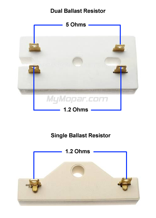
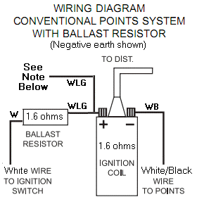
45 ballast resistor wiring diagram
(PDF) Basic Electrical House Wiring - Academia.edu Introduction: Basic measuring/recording instruments used in electrical circuit laboratory are, 1) Test lamp and tester for detecting presence/absence of electricity, 2) Voltmeter to measure voltage (V dc or ac) across two terminals, 3) Ammeter to measure current (I dc or ac) through an element, 4) Multi-meter (also known as AVO meter) to measure V, I, R, C, h fe , temperature, frequency etc ... LED Driver Basics and Its Circuit Design 09.04.2018 · Warm hints: The word in this article is about 3800 words and the reading time is about 23 minutes.. Introduction. LED is recognized as the fourth generation of the green light source. It is a solid cold light source. It has many advantages, like high efficiency, long life, safe and environmental protection, small size, high reliability, fast response speed and so on.
Nissan And Datsun Work Manuals D21 Hardbody Xe 4wd L4 2389cc ... Wiring diagram nissan z24 whistlindiesel wife of This simplified starter motor wiring diagram applies to the 1992, 1993, and 1994 2.4l nissan d21 pickup. 1991 nissan axxess 4dr wagon wiring information: So, if you wish to obtain the wonderful pics related to (1996 nissan d21 wiring diagram. Wiring diagram for nissan 1400 bakkie 3 Nissan, Nissan.
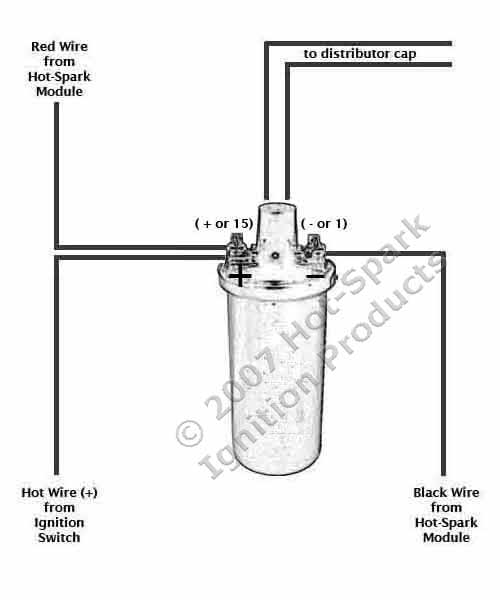
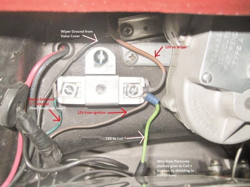
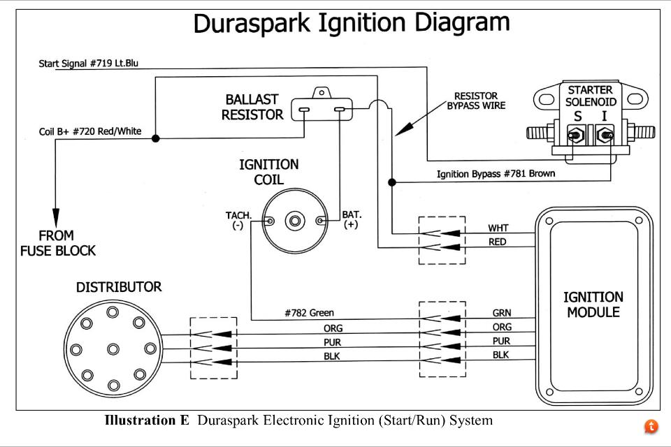
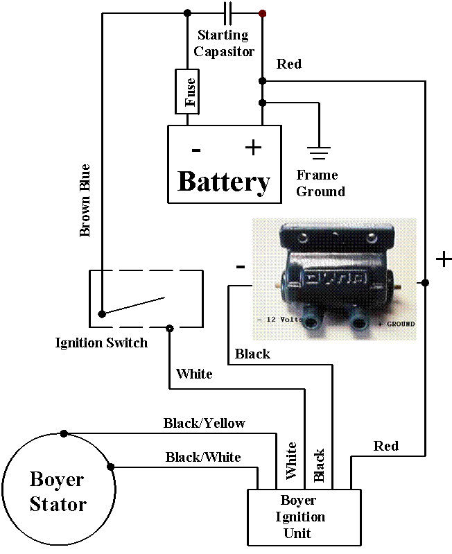
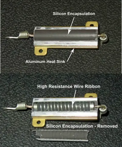
Ballast resistor wiring diagram
Detroit Diesel Series 60 Ecm Wiring Diagram Gallery 30.07.2018 · Wiring Diagram Images Detail: Name: detroit diesel series 60 ecm wiring diagram – Detroit Series 60 Ecm Wiring Diagram Originalstylophone 2007 6 0l Wiring Diagram Ecm At Nhrt; File Type: JPG; Source: nhrt.info; Size: 181.07 KB; Dimension: 1024 x 663; What can be a Wiring Diagram? LED Resistor : Circuit Diagram, Working and Example Problems The resistor used in this circuit is frequently known as a ballast resistor. The purpose of the resistor in an LED circuit is to limit the current flow throughout the LED and avoids excess current otherwise that can damage the LED. If the voltage source in the circuit is equivalent to the voltage drop of the LED, then no resistor is necessary. Troubleshooting for Pertronix Ignitor and Coil Installation The unit is actually turning off, and back on as the coil charges and releases energy. The best possible remedy for this problem is to wire the Ignitor units RED WIRE directly to a switched 12-volt source away from any voltage reduced circuit, such as a resister wire or ballast resistor. These circuits usually are in the wire from the ignition ...
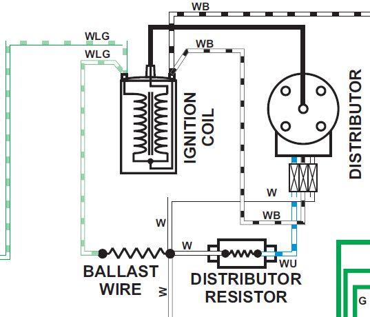
Ballast resistor wiring diagram. What is a Discharge Lamp : Design & Its Working - ElProCus As shown in the diagram, a discharge lamp consists of one gas tube, wherein a gas at low pressure is maintained. The gas tubes are filled with noble gasses like argon, neon, krypton, etc. Additionally, they are also filled with sodium mercury amalgam. Design. The sodium and mercury amalgam is required to draw an arc. At the end of the gas tube ... The large red wire goes to the solenoid on one of the large ... One of the larger terminals is connected to the hot wire coming from the battery, the second large terminal is connected to the starter, the first smaller terminal (S) connects to the ignition switch, the second small terminal connects to either ballast resistor (R) or ignition coil (I) and is generally unused.solenoid wiring diagram switch ... Troubleshooting Techniques - Holley The diagram below shows the proper installation for early Ford and GM vehicles. Import Vehicles. Import Vehicles . If your fuel injected import vehicle fails to start or the tachometer reads erratically, you will need an MSD Tach Adapter PN 8910. If the PN 8910 is installed and you have spark but the vehicle will still not run, you will need a special Tach Adapter. Contact MSD Tech … PPIC Statewide Survey: Californians and Their Government 26.10.2022 · Key Findings. California voters have now received their mail ballots, and the November 8 general election has entered its final stage. Amid rising prices and economic uncertainty—as well as deep partisan divisions over social and political issues—Californians are processing a great deal of information to help them choose state constitutional officers and …
BMW - electrical systems - WIRING DIAGRAM - Elektrotanya Key to wiring diagram for the central locking, burglar alarm, on-board computer, additional heater end digital clock (picture 3/1 – 3/2) 1. Plug - rear section to centre section 2. Connection for special equipmenl plug 3. Connaction for central loçk control unit 4. Central lock electronic control unit (A pillar end plate) 5. Plug - driver's door wire to rear section 6. Plug - central lock ... EMI Filter : Types, Circuit, Working & Its Applications - ElProCus In the above circuit, a current limit resistor or series resistor is connected to restrict the short circuit and overload current. In some types of electronic ballasts, a fuse can be used in place of this resistor. The resistance value of this current limit resistor is very less up to 22 Ohm. After that, an EMI filter is connected which includes one inductor within series & one capacitor ... 1994 ezgo 36 volt wiring diagram - adlq.addressnumber.shop wiring diagram camaro 1975 diagrams repair 1974 system ignition schematic guide 1973 autozone need fig 1981 chassis models continued repairguide. Club Car Battery Wiring Diagram 36 Volt - Wiring Schema wiringschema101.blogspot.com. Golf Cart Solenoid Wiring Diagram: Ezgo 36 Volt Selenoid Wiring Wiring alexandaraaa.blogspot.com. ezgo mpt schematron. 1993 Nissan D21 Wiring Diagram - Wiring Diagram Schemas ... 1993 Nissan D21 Wiring Diagram - Wiring Diagram Schemas wiringschemas.blogspot.com. pathfinder d21 mercruiser villager cableado probar arbol posicion levas distribuidor altima. 1995 Nissan Pickup Starter Wiring Diagram - Https Encrypted Tbn0 Gstatic Com Images Q Tbn wiring08.blogspot.com.wiring nissan diagram z24 engine d21 fuel 87 z24i ka24e alternator pickup 1987 harness control injection ...
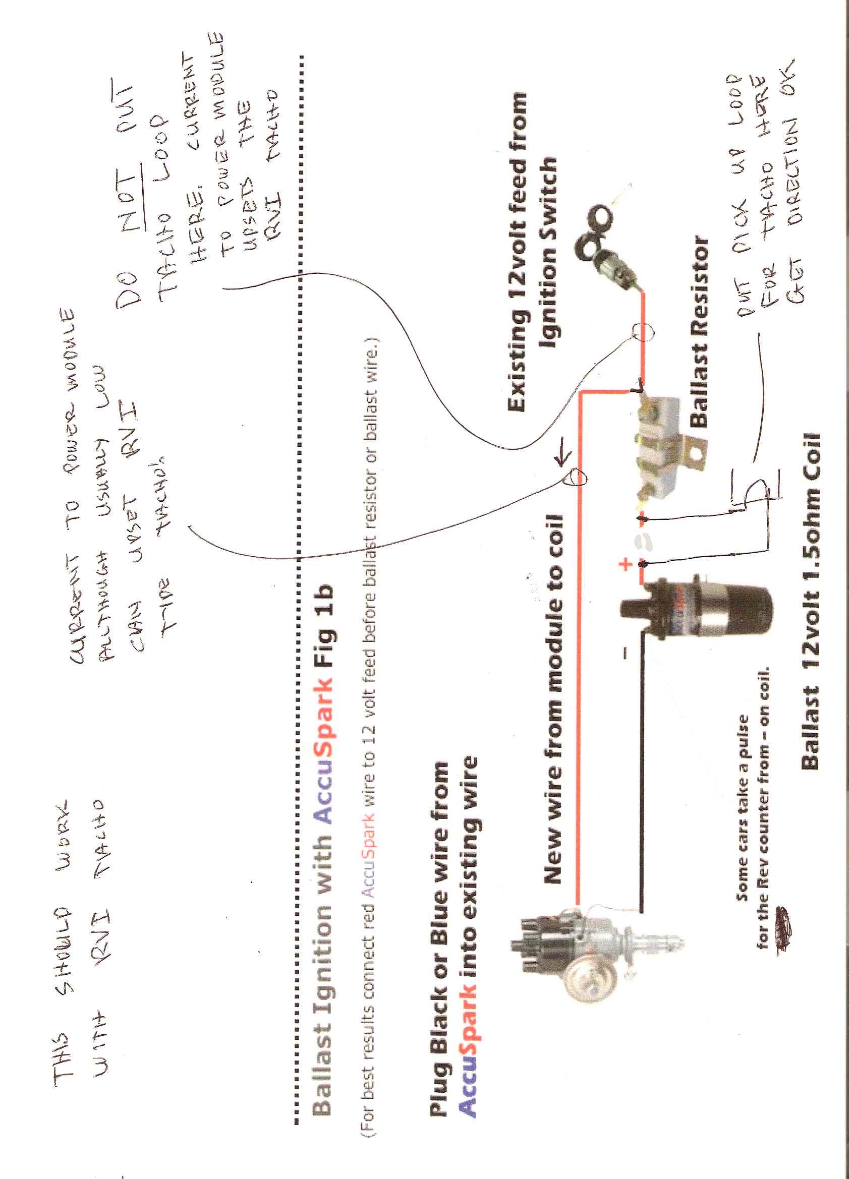
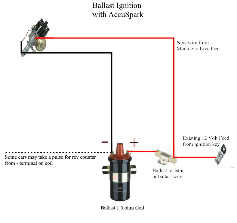
Mallory Unilite Distributor Installation Instructions - Holley FIGURE 1 UNILITE® WIRING DIAGRAM USING BALLAST RESISTOR NOTE: The purpose of an ignition ballast resistor between the ignition switch (12V) and the ignition coil positive terminal is to restrict current flow through the ignition coil. Failure to use an ignition ballast resistor will eventually destroy the Ignition Module. Troubleshooting for Pertronix Ignitor and Coil Installation The unit is actually turning off, and back on as the coil charges and releases energy. The best possible remedy for this problem is to wire the Ignitor units RED WIRE directly to a switched 12-volt source away from any voltage reduced circuit, such as a resister wire or ballast resistor. These circuits usually are in the wire from the ignition ... LED Resistor : Circuit Diagram, Working and Example Problems The resistor used in this circuit is frequently known as a ballast resistor. The purpose of the resistor in an LED circuit is to limit the current flow throughout the LED and avoids excess current otherwise that can damage the LED. If the voltage source in the circuit is equivalent to the voltage drop of the LED, then no resistor is necessary. Detroit Diesel Series 60 Ecm Wiring Diagram Gallery 30.07.2018 · Wiring Diagram Images Detail: Name: detroit diesel series 60 ecm wiring diagram – Detroit Series 60 Ecm Wiring Diagram Originalstylophone 2007 6 0l Wiring Diagram Ecm At Nhrt; File Type: JPG; Source: nhrt.info; Size: 181.07 KB; Dimension: 1024 x 663; What can be a Wiring Diagram?








0 Response to "45 ballast resistor wiring diagram"
Post a Comment