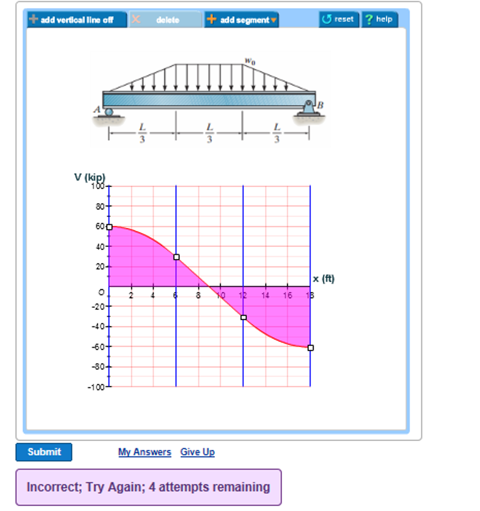
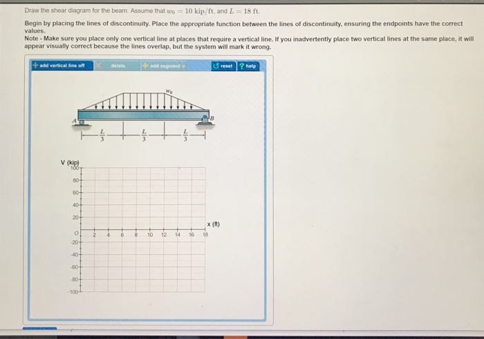
41 draw the shear diagram for the beam. assume that w0=10kip/ft, and l=18ft.
The Ultimate Guide to Shear and Moment Diagrams - DegreeTutors.com 5.3 Drawing the shear force diagram. Our approach to drawing the shear force diagram is actually very straightforward. We're going to 'trace the impact of the loads' across the beam from left to right. The first load on the structure is acting upwards, this raises the shear force diagram from zero to at point A. Answered: 4-26. Draw the shear and moment… | bartleby Q: For the beam below 1. Draw the shear and moment diagrams 2. Determine the maximum shear and moment. A: To determine shear force and bending moment, the first step is to calculate support reactions and…
Solved Draw the shear diagram for the beam. Assume | Chegg.com Question: Draw the shear diagram for the beam. Assume that w0=10kip/ft, and L=18ft. This problem has been solved! You'll get a detailed solution from a subject matter expert that helps you learn core concepts. See Answer Draw the shear diagram for the beam. Assume that w 0=10kip/ft, and L =18ft. Expert Answer 100% (8 ratings)

Draw the shear diagram for the beam. assume that w0=10kip/ft, and l=18ft.
Drawing Shear and Moment Diagrams for Beam - YouTube in general the process goes like this: 1) calculate support reactions 2) draw vertical lines at discontinuities 3) draw graphically by applying relationships for loading, shear, and moment... Shear and Moment Diagrams | Strength of Materials Review at ... - MATHalino INSTRUCTION: Write shear and moment equations for the beams in the following problems. In each problem, let x be the distance measured from left end of the beam. Also, draw shear and moment diagrams, specifying values at all change of loading positions and at points of zero shear. Neglect the mass of the beam in each problem. Tags: How to Draw Shear Diagrams | ReviewCivilPE Shear diagrams always begin and end at zero, with all of the forces on the member shown in between. Starting from the left, the first force you come across is the 10 lb downward force at the left end. This is the first point of data, draw a line from zero to negative 10. Continuing on the next force is 21.67 lb upward at the A support.
Draw the shear diagram for the beam. assume that w0=10kip/ft, and l=18ft.. Calculating Shear Force Diagram | SkyCiv Engineering Calculating Shear Force Diagram - Step 1: After you calculate the reactions at the supports at A and B, start the Shear Force Diagram at the first value of the force acting on the beam. We take the sum of all vertical forces, which in this case, is just a +10kN due to the reaction at point A: Calculating Shear Force Diagram - Step 2: Answered: For the beam shown below, given that L… | bartleby Answered: For the beam shown below, given that L… | bartleby. Engineering Civil Engineering For the beam shown below, given that L = 10 m, and w = 6 kN/m, draw the FBD & shear diagram, and then input the magnitude of the max internal shear force along the beam: ____ kN. Calculate your solution to 1 decimal place. Solved Draw the shear diagram for the beam. Assume that w 0 | Chegg.com You'll get a detailed solution from a subject matter expert that helps you learn core concepts. See Answer Draw the shear diagram for the beam. Assume that w 0 =10kip/ft , and L=18ft Draw the moment diagram for the beam. Assume that w 0 =10kip/ft , and L=18ft Show transcribed image text Expert Answer 100% (10 ratings) Draw the shear diagram and the moment diagram for the beam. Assume that ... Draw the shear diagram and the moment diagram for the beam. Assume that w_0 = 10 kip/ft , and L= 18 ft. Figure S.F.D and B.M.D B.M.D (Bending moment diagram ) is a diagram...
How to Calculate and Draw Shear and Bending Moment Diagrams Step 2: Step 1: Knowing Forces Effect on Beams - Knowing how different forces effect beams is important to be able to calculate the shear and bending moments. - A point force will cause a rectangular shear and a triangular bending moment. - A rectangular distributed load will cause a triangular shear and a quadratic bending moment. Add Tip Shear Force Diagram - How to Draw a SFD - mechGuru Here are simple five steps applicable for drawing almost all types of shear force diagram correctly (Refer the following typical example in connection with the below steps): 1. Draw a horizontal line to represent the beam and divide the line by putting points at the following locations: - At the point loads locations. Beam Calculator Online (Calculate the reactions, Draws Bending Moment ... Calculate the reactions at the supports of a beam - statically determinate and statically indeterminate, automatically plot the Bending Moment, Shear Force and Axial Force Diagrams ... Shear Force Diagram (SFD) Axial Force Diagram (AFD) Moment is positive, when tension at the bottom of the beam. Cross-Section Optimization. How to Draw Shear Diagrams | ReviewCivilPE Shear diagrams always begin and end at zero, with all of the forces on the member shown in between. Starting from the left, the first force you come across is the 10 lb downward force at the left end. This is the first point of data, draw a line from zero to negative 10. Continuing on the next force is 21.67 lb upward at the A support.
Shear and Moment Diagrams | Strength of Materials Review at ... - MATHalino INSTRUCTION: Write shear and moment equations for the beams in the following problems. In each problem, let x be the distance measured from left end of the beam. Also, draw shear and moment diagrams, specifying values at all change of loading positions and at points of zero shear. Neglect the mass of the beam in each problem. Tags: Drawing Shear and Moment Diagrams for Beam - YouTube in general the process goes like this: 1) calculate support reactions 2) draw vertical lines at discontinuities 3) draw graphically by applying relationships for loading, shear, and moment...
D. Assume The Support at B Is A Roller. Point C Is Located ...

Calculate and sketch the variation of the shearing force and ...
Untitled
SOLUTION
PROBLEM 5.1
1081 Bending Stress: From the moment diagram, Applying the ...
PROBLEM # 1 (25 points) A simply supported beam AH is subject ...
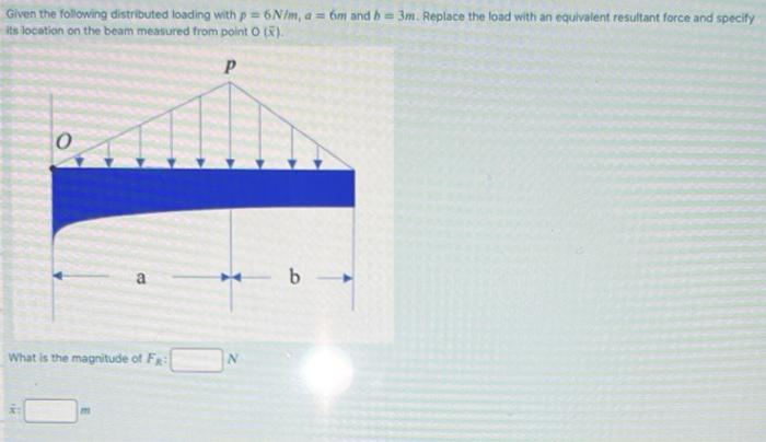
Solved Given the following distributed loading with \( p=6 ...
Untitled
Solved Learning Goal: To choose the lightest and most | Chegg.com
SOLUTION
Solved: Chapter 4 Problem 41P Solution | Structural Analysis ...
Untitled
Untitled

Draw Shear diagram and Moment Diagram (Mark the transition ...

Draw Shear diagram and Moment Diagram (Mark the transition ...
Solved GEN 205: Spring 2019 w #9: Due Wednesday 3/27/2019 by ...
PROBLEM 5.1

Draw the shear force and moment diagram for the problem below ...
Period #13: Practice with V and M Diagrams
PROBLEM 5.1
PDF) Ch11-12 beams & shafts - design & deflection | DIEGO ...

Calculate and sketch the variation of the shearing force and ...
Shear force and bending moment diagrams example #2: multiple point loads
Chapter 7
SOLUTION
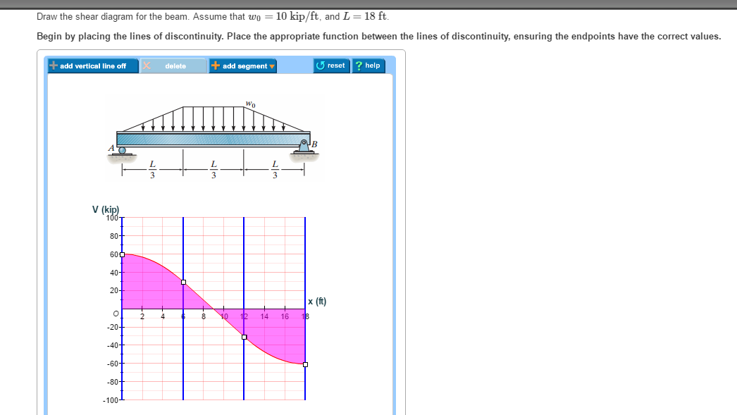
Solved Draw the shear diagram for the beam. Assume that wo ...
Untitled
Solved Draw the shear diagram for the beam. Assume that w 0 ...

PDF) Statics Note, Statics (Solution and Answer) | Syuqeri ...

PDF) Mechanics Important chapters | Abu Owais Ahmed ...
1081 Bending Stress: From the moment diagram, Applying the ...
Period #13: Practice with V and M Diagrams

For the figure below draw shear and moment diagram. Mark the ...

1) Draw Shear diagram and Moment Diagram (Mark the transition ...
Solved Draw the shear diagram for the beam Assume that uo ...
Untitled
SOLUTION

Draw Shear diagram and Moment Diagram (Mark the transition ...

Find the location on the beam below where shear is equal to ...

Tests
0 Response to "41 draw the shear diagram for the beam. assume that w0=10kip/ft, and l=18ft."
Post a Comment