41 defrost termination switch wiring diagram
™Defrost Termination Switch Wiring Diagram ⭐⭐⭐⭐⭐ Defrost termination switch wiring diagram a wiring diagram is a streamlined traditional photographic depiction of an electric circuit. Schematic Showing Defrost Termination/Fan Delay Switch. Defrost termination switch wiring diagram defrost heater l1 l2 termination thermos ta w/fan delay f 3 1 2 4 n x line 8145 replacement (retrofit) dtav40 ... Defrost Termination Switch Wiring Diagram Defrost Termination Switch Wiring Diagram A Wiring Diagram Is A Streamlined Traditional Photographic Depiction Of An Electric Circuit. O the coil warms to approximately 55°f, the defrost termination closes and energizes the switching solenoid in the timer. It is usually regularly normally called the alternating recent means circuit.
3 Wire Defrost Termination Switch Wiring Diagram - qstion.co 3 wire defrost termination switch wiring diagram. The control is wired into the refrigeration circuit. Interlink 3 wire defrost termination switch with black and blue wires in one side of switch and red out other side of switch. In this diagram, the electrical source is at the first switch and the light is located at the end of the circuit. ...
Defrost termination switch wiring diagram
Defrost Termination Switch Wiring Diagram - Mr. Whippy ice cream maker 3 Wire Defrost Termination Switch Wiring Diagram from diagramweb.net. Is there a reason they can't include a wiring diagram of the switch in the interlink 3 wire defrost termination switch with black and blue wires in. The control can be an adjustable type. 4 wire oxygen sensor wiring diagram. Defrost Termination Switch Wiring Diagram Defrost Termination Switch Wiring Diagram 5 Tips about ebook download You Can Use Today If your refreshingly minimalist structure of World Ebook doesn't right away influence you of its merits, its sizable catalogue of public domain books surely will. Opsi pencarian yang tersedialengkap dan spesifik. Kamu bisa mencari beragam buku komputer ... Defrost Termination Switch Wiring Diagram - Thaimetera AOKI Defrost Termination Switch Wiring Diagram A Wiring Diagram Is A Streamlined Traditional Photographic Depiction Of An Electric Circuit. The f25 control terminates defrost and delays evaporator fan operation following a defrost the f25 control switch is closed in the fan delay position and open figure 1. Is there a reason they can't include a ...
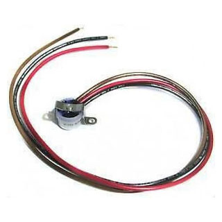
Defrost termination switch wiring diagram. Defrost termination / fan delay operation - YouTube Short description of how a defrost termination / fan control operates. Thanks for watching Follow me on Instagram @cscrefrigerationandhvacInquiries can reac... √ Defrost Termination Switch Wiring Diagram It is usually regularly normally called the alternating recent means circuit. The graph signifies two wires, an individual to carry electrical electricity and also the opposite since the neutral wire. Defrost Termination Switch Wiring Diagram. 3 wire defrost termination switch wiring diagram from diagramweb.net. 4 wire oxygen sensor wiring diagram. A 3-wire fan / defrost termination switch? - HVAC-Talk: Heating, Air ... A 3-wire fan / defrost termination switch? Red wire, brown wire, black wire. On a 120 volt system one wire has to be a common connection, one wire has to be the common to the X terminal on the defrost timer, and the other wire has to control the common to the evap fans. Which wire is which? Common? Close on rise? Close on fall? PHM ------ PHM Bad thermistor symptoms refrigerator - lanj.narownowazni.pl Defrost Termination Thermostat. The termination thermostat can be found on the evaporator coil, and its role is to turn off the defrost heater when the temperature of the freezer reaches a certain limit. The defrost thermostat. dpf delete and remap near me. 146 attendees. Thu, Aug 4 · 3:00 PM PDT. NYC Robotics Meetup #3 @ Eventscape, Long ...
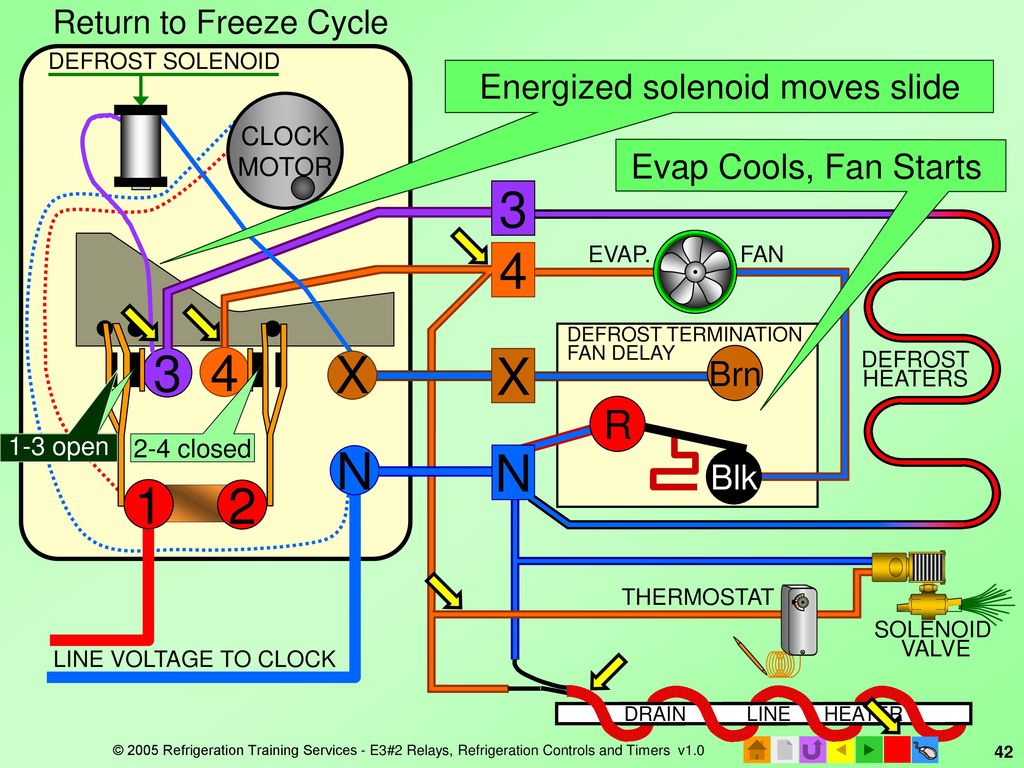
Defrost Termination Switch Wiring Diagram - Air filter wrap Schematic showing defrost terminationfan delay switchThis type of wiring diagram has branch runs all shown as parallel circuits going from the left line L1 to the neutral line N. Defrost Thermostat Adjustable F25-209 Series The defrost duration is determined by the setting of the defrost termination thermostat. 5709L 3 WIRE DEFROST TERM SWITCH. 3 Wire Defrost Termination Switch Wiring Diagram 3 Wire Defrost Termination Switch Wiring Diagram The F25 Control terminates defrost and delays evaporator fan operation following the compressor and evaporator fan motor (s) and closes a switch to the defrost heater. 3. 3. Wire control is recommended by the evaporator manufacturer. 4. replacements for Bohn, Larkin, Chandler, and Climate Control. defrost termination switch wiring diagram Wiring paragon defrost 8145 fixya intermatic. True defrost termination switch. 8145 defrost paragon diagrams cuartos refrigeration grasslin waterheatertimer fixya electromecanico rewire electronico termination ions esquemas especificaciones programable cavas timers geno √Defrost Termination Switch Wiring Diagram ⭐⭐⭐⭐⭐ The f25 control switch is closed in the fan delay position and open in the defrost termination position 3. Defrost Termination Switch Wiring Diagram A Wiring Diagram Is A Streamlined Traditional Photographic Depiction Of An Electric Circuit. The control shown also happens to be an adjustable type.
Defrost Termination Switch Wiring Diagram Defrost Termination Switch Wiring Diagram. A wiring diagram is a streamlined traditional photographic depiction of an electric circuit. The f25 control terminates defrost and delays evaporator fan operation following a defrost the f25 control switch is closed in the fan delay position and open figure 1. ®Defrost Termination Switch Wiring Diagram ⭐⭐⭐⭐⭐ Defrost termination switch wiring diagram a wiring diagram is a streamlined traditional photographic depiction of an electric circuit. The control shown also happens to be an adjustable type. 3 wire defrost termination switch. Source: diagramweb.net Diagram wiring termination defrost fan switch delay. Defrost Termination Fan Delay Switch Wiring Diagram Download Wiring Diagram Pics Detail: Name: defrost termination fan delay switch wiring diagram - Diagram Defrost Termination Switch Wiring Diagram Wiring A Homeline Service Panel 5709l Wiring Diagram Source defrost termination fan delay File Type: JPG Source: harenohi-ir.co Size: 469.81 KB Dimension: 2533 x 1780 3 Wire Defrost Termination Switch Wiring Diagram Download Name: 3 wire defrost termination switch wiring diagram - heat pump were able to handle the heating load down to 15°F the outdoor thermostat would be set just below that to allow auxiliary heat to e on File Type: JPG Source: industrialcontrolsonline.com Size: 25.70 KB Dimension: 732 x 414
Installation, Operation, and Maintenance Information
Unbanked American households hit record low numbers in 2021 Oct 25, 2022 · Those who have a checking or savings account, but also use financial alternatives like check cashing services are considered underbanked. The underbanked represented 14% of U.S. households, or 18. ...
INTER-TEMP INSTALLATION MAINTENANCE MANUAL Inspection ...
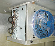
Using Defrost Termination and Fan Delay Controls | ACHR News The defrost termination/fan delay control is a temperature activated, single-pole, double-throw (spdt) switch controlled with a remote sensing bulb. The control shown also happens to be an adjustable type. Figure 1 shows an installation of an adjustable defrost termination/fan delay control on an evaporator.
E3 HVACR Controls and Devices - ppt download
About Our Coalition - Clean Air California About Our Coalition. Prop 30 is supported by a coalition including CalFire Firefighters, the American Lung Association, environmental organizations, electrical workers and businesses that want to improve California’s air quality by fighting and preventing wildfires and reducing air pollution from vehicles.
Commercial Refrigeration Temperature and Defrost Controls
Defrost Termination Fan Delay Switch Wiring Diagram Schematic showing defrost termination/fan delay switch. The F25 Control terminates defrost and delays evaporator fan operation following a defrost The F25 Control switch is closed in the fan delay position and open Figure 1. 3. Wire control is recommended by the evaporator manufacturer. 4.Allen Refrigeration & Equipment is located in Dayton, OH ...

Typical wiring for defrost on a single evaporator freezer
Defrost Termination Switch Wiring Diagram |-| Flint firestarter Defrost termination switch wiring diagram a wiring diagram is a streamlined traditional photographic depiction of an electric circuit. The control shown also happens to. 3 wire defrost termination switch wiring diagram from diagramweb.net. Wiring Diagram For True Mfg Model #Tcgr50.
Commercial Refrigeration Temperature and Defrost Controls
eCFR :: 10 CFR Part 430 -- Energy Conservation Program for ... (B) Has a color point with (x,y) chromaticity coordinates on the C.I.E. 1931 chromaticity diagram, figure 2, page 3 of IESNA LM-16 (incorporated by reference; see § 430.3) that lies at least 4 MacAdam steps, as referenced in IESNA LM-16, distant from the color point of a clear lamp with the same filament and bulb shape, operated at the same ...
HVAC-Talk: Heating, Air & Refrigeration Discussion
PlayStation userbase "significantly larger" than Xbox even if ... Oct 12, 2022 · Microsoft has responded to a list of concerns regarding its ongoing $68bn attempt to buy Activision Blizzard, as raised by the UK's Competition and Markets Authority (CMA), and come up with an ...
Commercial Refrigeration
Microsoft says a Sony deal with Activision stops Call of Duty ... Oct 21, 2022 · A footnote in Microsoft's submission to the UK's Competition and Markets Authority (CMA) has let slip the reason behind Call of Duty's absence from the Xbox Game Pass library: Sony and
Part Number: E104282_P
Defrost Termination Fan Delay Switch Wiring Diagram Database To properly read a cabling diagram, one offers to know how the particular components within the program operate. For example , when a module is powered up and it also sends out a signal of half the voltage in addition to the technician will not know this, he would think he provides a challenge, as this individual would expect a new 12V signal.

Defrost Time & Temperature - HVAC School
3 Wire Defrost Termination Switch Wiring Diagram | champion Kenmore Refrigerator Defrost Timer Wiring Diagram. Rtd Pt100 3 Wire Wiring Diagram. Nest Hello Wiring Diagram 4 Wire. 4 Wire Trailer Wiring Diagram Pdf. Gm 4 Wire Alternator Wiring Diagram. 3 Wire 220v Hot Tub Wiring Diagram. 4 Wire O2 Sensor Wiring Diagram Bmw. 3 Wire Alternator Wiring Diagram Dodge. 4 Wire Trailer Wiring Diagram Troubleshooting.
Using Defrost Termination and Fan Delay Controls | ACHR News
Defrost Termination Switch Wiring Diagram - Thaimetera Avico Diagram termination wiring wire defrost transducer pressure thermostat omron switch h3ca h3cr a8 sensor timer menggunakan inspirational oxygen close ice. For instance , if a module is powered up and it sends out a signal of half the voltage in addition to the technician would not know this, he would think he offers a challenge, as this ...
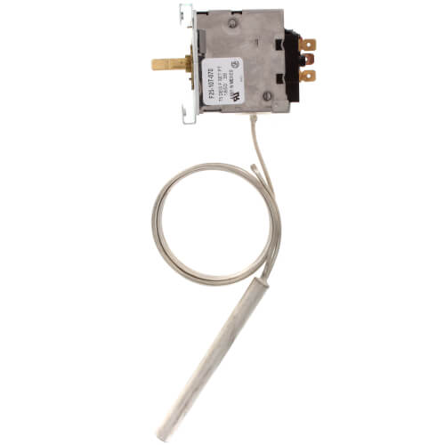
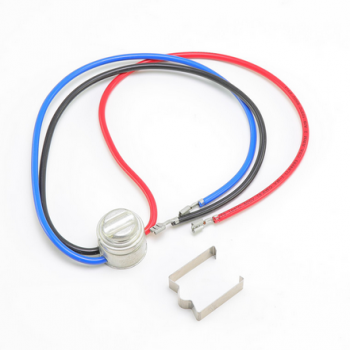
Defrost Termination/Fan Delay Control, w/ 60" Capillary
Defrost Termination Fan Delay Switch Wiring Diagram Schematic showing defrost termination/fan delay switch. The F25 Control terminates defrost and delays evaporator fan operation following a defrost The F25 Control switch is closed in the fan delay position and open Figure 1. 3. Wire control is recommended by the evaporator manufacturer. Evaporator with a Blown Defrost Termination Switch
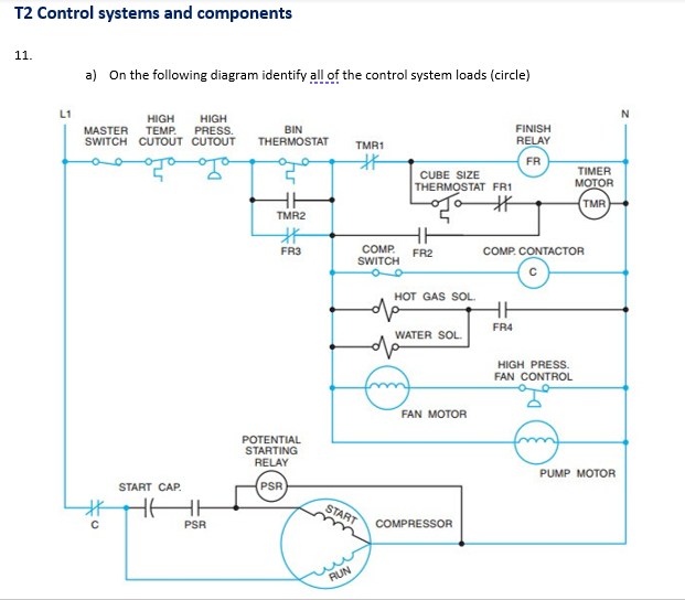
T2 Control systems and components 11. a) On the | Chegg.com
Defrost Termination Switch Wiring Diagram Defrost Termination Switch Wiring Diagram. The graph signifies two wires, an individual to carry electrical electricity and also the opposite since the neutral wire. Defrost termination switch wiring diagram a wiring diagram is a streamlined traditional photographic depiction of an electric circuit.

Evaporator with a Blown Defrost Termination Switch
Could Call of Duty doom the Activision Blizzard deal? - Protocol Oct 14, 2022 · A MESSAGE FROM QUALCOMM Every great tech product that you rely on each day, from the smartphone in your pocket to your music streaming service and navigational system in the car, shares one important thing: part of its innovative design is protected by intellectual property (IP) laws.
INSTALLATION DATA F25-107/114 EVAPORATOR DEFROST TERMINATION ...
Defrost Termination Switch Wiring Diagram Defrost termination switch wiring diagram 5 tips about where to download free ebooks epub you can use today from romance to mystery to drama, this website is an. Defrost termination switch wiring diagram a wiring diagram is a streamlined traditional photographic depiction of an electric circuit.

E3 HVACR Controls and Devices - ppt download
Defrost Termination Switch Wiring Diagram Database Effectively read a electrical wiring diagram, one offers to learn how the particular components within the system operate. For instance , if a module is powered up and it sends out a signal of half the voltage in addition to the technician would not know this, he would think he offers a challenge, as this individual would expect the 12V signal.
PRO3 Top Mount Packaged Refrigeration System
Defrost Termination Switch Wiring Diagram - Thaimetera AOKI Defrost Termination Switch Wiring Diagram A Wiring Diagram Is A Streamlined Traditional Photographic Depiction Of An Electric Circuit. The f25 control terminates defrost and delays evaporator fan operation following a defrost the f25 control switch is closed in the fan delay position and open figure 1. Is there a reason they can't include a ...

Bohn 3 Wire Fan and Defrost Terminal | 30 F Cut-In Temp | 50 ...
Defrost Termination Switch Wiring Diagram Defrost Termination Switch Wiring Diagram 5 Tips about ebook download You Can Use Today If your refreshingly minimalist structure of World Ebook doesn't right away influence you of its merits, its sizable catalogue of public domain books surely will. Opsi pencarian yang tersedialengkap dan spesifik. Kamu bisa mencari beragam buku komputer ...
REFRIGERATION DEFROST THERMOSTATS
Defrost Termination Switch Wiring Diagram - Mr. Whippy ice cream maker 3 Wire Defrost Termination Switch Wiring Diagram from diagramweb.net. Is there a reason they can't include a wiring diagram of the switch in the interlink 3 wire defrost termination switch with black and blue wires in. The control can be an adjustable type. 4 wire oxygen sensor wiring diagram.
Reach-In Unit Coolers

Online HVAC Training - YouTube

Defrost Termination & Fail-Safe - HVAC School
Heatcraft Refrigeration 7075819 Defrost and Fan Control 3-Wire

DEFROST TERMINATION TSTAT BOHN LARKIN 3 WIRE SUPCO | Behler-Young
HVAC-Talk: Heating, Air & Refrigeration Discussion
TABLE OF CONTENTS

Replacement True Defrost Termination Switch/Fan Delay 800316 ...

Heatcraft - 5709L - 3 Wire Fan & Defrost Terminal 55 °F-35 °F
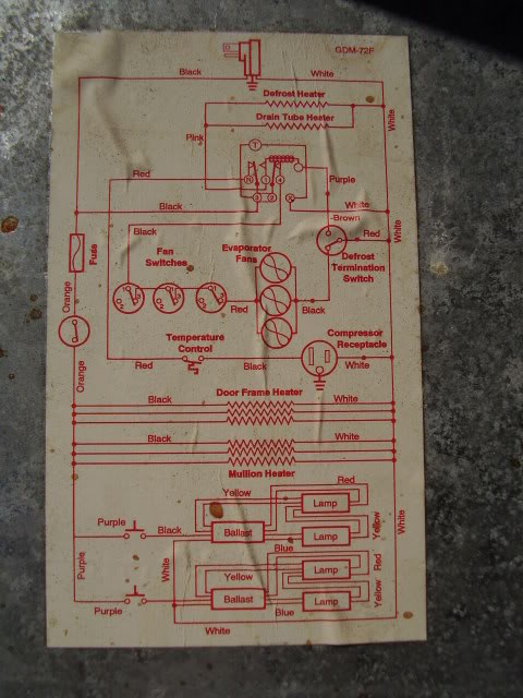
TRUE GDM-72F Wire Schematic – Refrigeration Mechanics

defrost-circuit.png |

Types Of Automatic Pumpdown Control Systems | ACHR News

Adaptive Defrost Information | Appliance Aid
4834 Installation Instructions: Single Condenser Defrost Time ...

T-49f wiring diagram: Swapping timer on True T49F freezer ...
HVAC-Talk: Heating, Air & Refrigeration Discussion

Demand Defrost | Industrial Controls
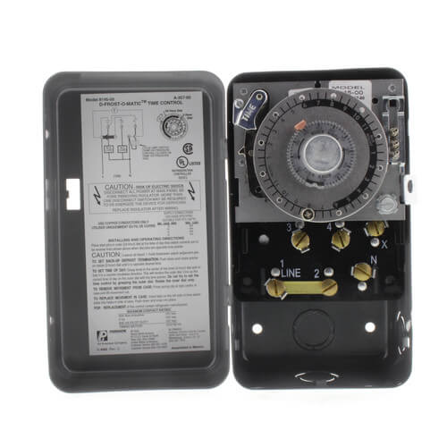
Defrost Time Controls / HVAC/R Defrost Time Controls / HV AC/R
Defrost Termination & Fail-Safe - HVAC School

HVAC Commercial Ref. - ppt download

Thermostat - Fan Delay Defrost Termination | Helmer Scientific

Robertshaw | Products | F25-107
0 Response to "41 defrost termination switch wiring diagram"
Post a Comment