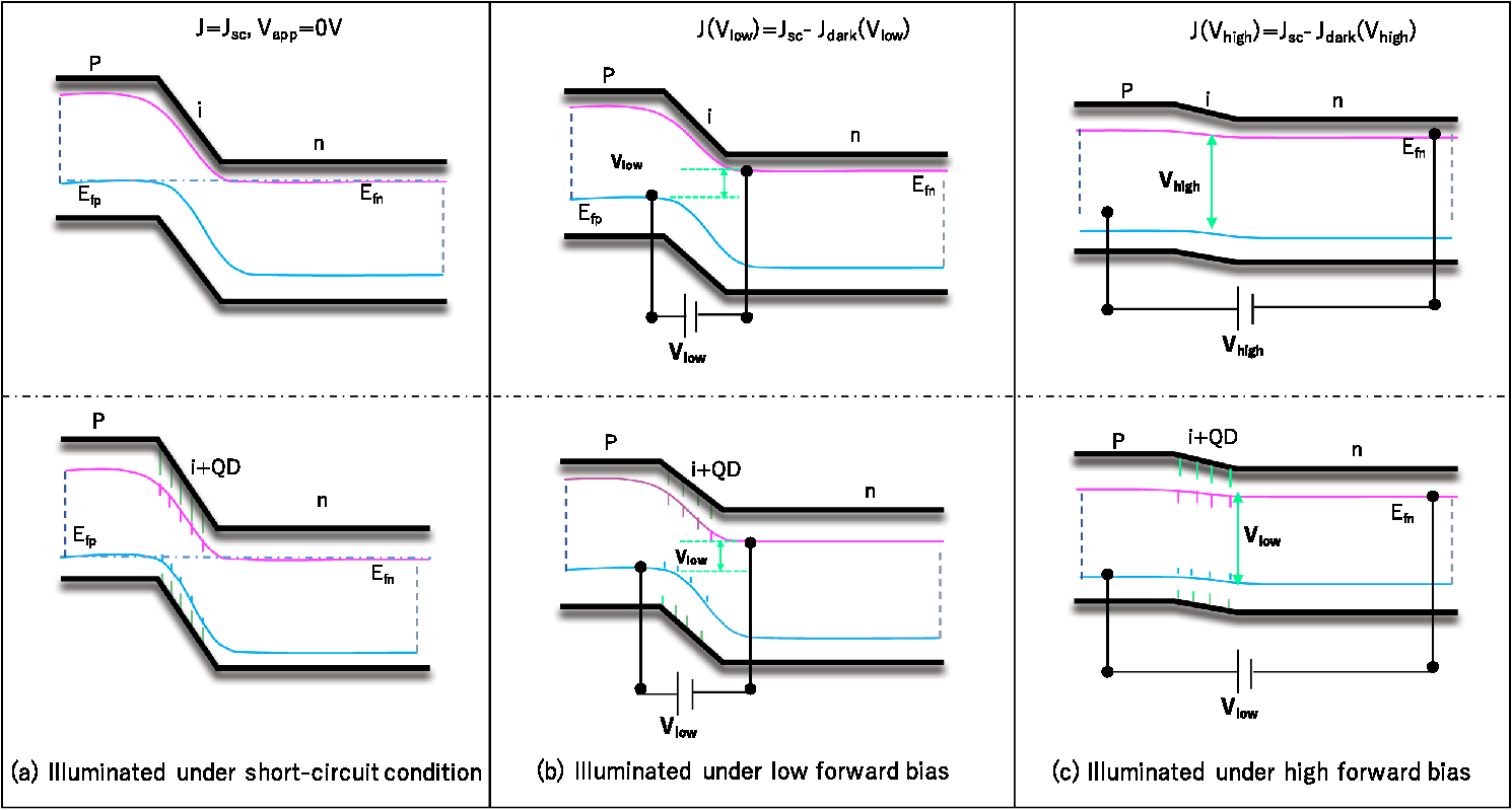
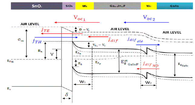
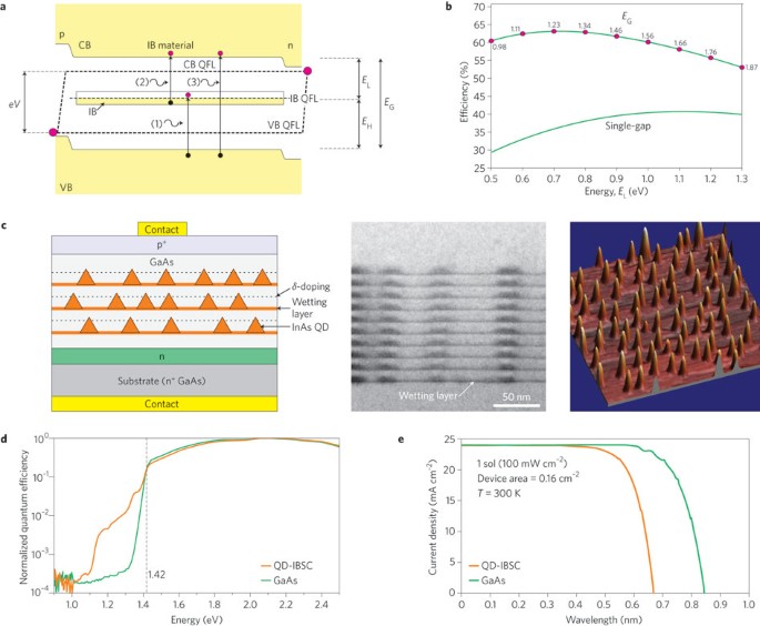
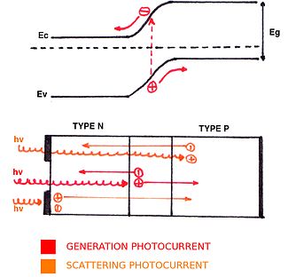
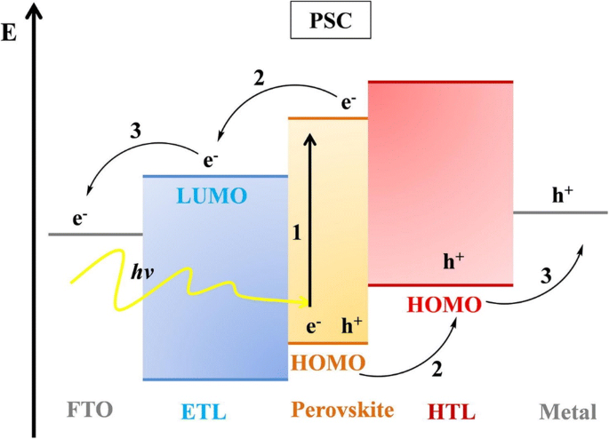
39 solar cell band diagram
solar cell | Definition, Working Principle, & Development Solar cells, whether used in a central power station, a satellite, or a calculator, have the same basic structure.Light enters the device through an optical coating, or antireflection layer, that minimizes the loss of light by reflection; it effectively traps the light falling on the solar cell by promoting its transmission to the energy-conversion layers below. The emergence of perovskite solar cells | Nature Photonics 27.06.2014 · c, Energy-band diagram deduced from the vacuum energy levels shown in Fig. 2b. χ P, χ T and χ F represent the electron affinities of the perovskite, TiO 2 and FTO layers, respectively, and Φ ...
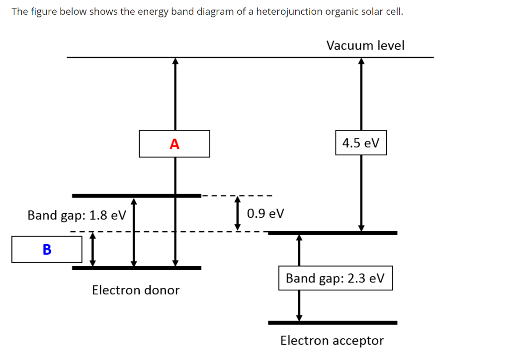
Band Diagram of Heterojunction Solar Cells through Scanning Tunneling ... The band diagram in heterojunction solar cells is of utmost importance when visualizing the possibility of charge separation and carrier transport. The diagram should in principle be drawn from the viewpoint of the charge carriers in the devices. While considering solar cells based on conjugated organics and/or inorganic compound semiconductors, we have shown in this Perspective that scanning ...

Solar cell band diagram
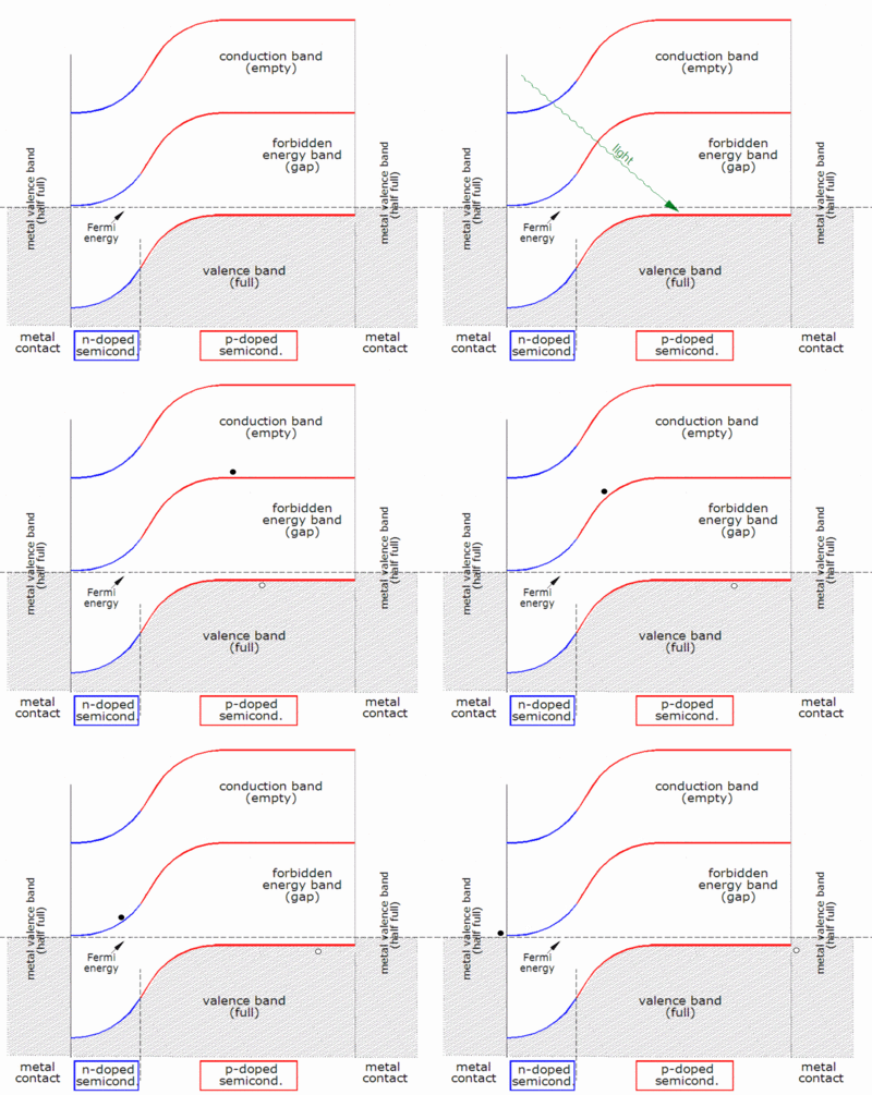
Solar Cell Structure | PVEducation Solar Cell Structure. A solar cell is an electronic device which directly converts sunlight into electricity. Light shining on the solar cell produces both a current and a voltage to generate electric power. This process requires firstly, a material in which the absorption of light raises an electron to a higher energy state, and secondly, the ... Understanding solar cell band diagram | Physics Forums The only thing that I can not completely understand is the physical operation of solar cell based on band diagram. Can anyone briefly explain the movements of carriers from one electrode to the another based on band diagram? Attachments IMG_20180311_202159_438.jpg 51.6 KB · Views: 1,191 IMG_20180311_202157_156.jpg 51.7 KB · Views: 1,340 Theory of solar cells - Wikipedia Band diagram of a solar cell, corresponding to very low current (horizontal Fermi level ), very low voltage (metal valence bands at same height), and therefore very low illumination Contents 1 Working explanation 2 Photogeneration of charge carriers 3 The p-n junction 4 Charge carrier separation 5 Connection to an external load
Solar cell band diagram. How Do Perovskite Solar Cells Work? - Joule Figure 1 A shows the band diagram of a p-i-n solar cell. In this model an intrinsic light-absorbing semiconductor is contacted by a couple of doped layers: n and p, respectively. In dark conditions with no applied bias the Fermi level, EF0, equilibrates along the complete device (see Figure 1 A). Solar Cells: A Guide to Theory and Measurement | Ossila Typical IV curve of a solar cell plotted using current density, highlighting the short-circuit current density (Jsc), open-circuit voltage (Voc), current and voltage at maximum power (JMP and VMP respectively), maximum power point (PMax), and fill factor (FF).. The properties highlighted in the figure are: J MP - Current density at maximum power Energy band diagram of the perovskite solar cell when ... - ResearchGate Energy band diagram of the perovskite solar cell when the "Fermi level" is taken as the reference energy level instead of the "vacuum level" (note the drawing is not to scale) Source publication... Schematic diagram of perovskite solar cell and its energy band level ... ... band diagram of the p-i-n perovskite solar cell in equilibrium condition is shown in Fig. 1. The defect energy level at 0.6 eV is present below the conduction band (E c ) of the...
Monolithic perovskite/silicon tandem solar cell with >29 11.12.2020 · A tandem solar cell, consisting of a silicon cell overlaid by a perovskite solar cell (PSC) , ... led to a more optimized alignment with the perovskite valence band edge (see energetic band edge diagram in fig. S1) with a similar dipole moment (~1.7 D) and resulted in faster charge extraction. The supplementary materials contain the synthesis scheme of the … P/N Junctions and Band Gaps - Solar Cell Central A p/n junction is formed when two types of semiconductors, n- type (excess electrons) and p- type (excess holes), come into contact. The term p/n junction refers to the joint interface and the immediate surrounding area of the two semiconductors. The term band gap refers to the energy difference between the top of the valence (outer electron) band and the bottom of the conduction (free ... Silicon Solar Cells - Stanford University Physics of Silicon Solar Cells. An ideal solar cell has a direct band gap of 1.4 eV to absorb the maximum number of photons from the sun's radiation. Silicon, on the other hand, has an indirect band gap of 1.1 eV. Silicon is not the ideal solar cell, but it provides several advantages: silicon is very stable (it has the same crystal structure ... Solar Cell: Working Principle & Construction (Diagrams Included) A voltage is set up which is known as photo voltage. If we connect a small load across the junction, there will be a tiny current flowing through it. V-I Characteristics of a Photovoltaic Cell Materials Used in Solar Cell The materials which are used for this purpose must have band gap close to 1.5ev. Commonly used materials are- Silicon. GaAs.
PDF An optimized structure for CdTe Solar Cells - New Jersey Institute of ... layer and absorber layer. A flat band diagram of a typical CdTe solar cell with traditional CdS material as n-window layer is shown Fig.1. is defined as (1) Fig.1. Flat band diagram of a typical CdTe solar cell For this traditional CdTe solar cell, is negative and is approximately equal to -0.1eV. And it is easy to find that the Solar tracker - Wikipedia Photovoltaic solar cell efficiency decreases with increasing temperature, at the rate of about 0.4%/°C. For example, 20% higher efficiency at 10 °C in early morning or winter as compared with 60 °C in the heat of the day or summer. Therefore, trackers can deliver additional benefit by collecting early morning and winter energy when the cells are operating at their highest … Energy Bands of Perovskite solar cells - YouTube This video will introduce that how the energy bands of perovskite solar cells appear under illuminated condition (simulated in AMPS). ... Band Diagram - an overview | ScienceDirect Topics On the band diagram in Fig. 12-17A the original built-in potential V0 at the junction is physically represented by a step. The construction requires that the sloping conduction and valence band lines smoothly connect the band edges of the homogeneous semiconductors on either side of the junction. Sign in to download full-size image FIGURE 12-17.
Digital Object Identifier System 13.05.2021 · This is the web site of the International DOI Foundation (IDF), a not-for-profit membership organization that is the governance and management body for the federation of Registration Agencies providing Digital Object Identifier (DOI) services and registration, and is the registration authority for the ISO standard (ISO 26324) for the DOI system.
Solar Panel Diagrams - How Does Solar Power Work? - Liter of Light USA The diagram above shows the key elements in a solar cell. Solar cells collect energy from sunlight and convert it into electricity using a chemical reaction called the photovoltaic (PV) process. Sunlight reaches our solar panel in the form of photons, small energetic particles/waves. These photons carry energy in the form of light, heat, and ...
Photovoltaic effect - Wikipedia History. The first demonstration of the photovoltaic effect, by Edmond Becquerel in 1839, used an electrochemical cell. He explained his discovery in Comptes rendus de l'Académie des sciences, "the production of an electric current when two plates of platinum or gold immersed in an acid, neutral, or alkaline solution are exposed in an uneven way to solar radiation."
A Solar Panel Diagram Helps To Simplify Your Solar Power System These are the different elements featured in the solar energy diagram: Solar Panel. This is obviously an important part of your solar power system. The solar panel absorbs the light of the sun and converts it into DC electricity. Charge Controller. The charge controller is the brain of your solar system.
Energy-band diagram of a silicon p-n junction solar cell (Reproduced ... As shown in Figure 1, a solar cell is made from a junction of p-and n-doped semiconductor material, whereas the p-type dopant pushes the Fermi level down closer to the valence band. On the...
Thin-film solar cell - Wikipedia A thin-film solar cell is a second generation solar cell that is made by depositing one or more thin layers, or thin film (TF) of photovoltaic material on a substrate, such as glass, plastic or metal. Thin-film solar cells are commercially used in several technologies, including cadmium telluride (CdTe), copper indium gallium diselenide (CIGS), and amorphous thin-film silicon (a-Si, TF-Si).
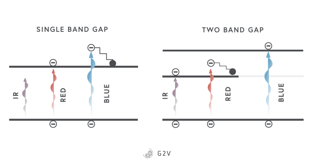
Solar cell - Wikipedia From a solar cell to a PV system. Diagram of the possible components of a photovoltaic system. ... Intermediate band photovoltaics in solar cell research provides methods for exceeding the Shockley-Queisser limit on the efficiency of a cell. It introduces an intermediate band (IB) energy level in between the valence and conduction bands. ...
PDF The Physics of the Solar Cell - دانشکده مهندسی برق 86 THE PHYSICS OF THE SOLAR CELL Conduction Band E p E C E G E V electrons holes Valence Band Figure 3.3 A simplified energy band diagram at T>0K for a direct bandgap (E G) semiconductor. Electrons near the maxima in valence band have been thermally excited to the empty states near the conduction-band minima, leaving behind holes. The excited ...
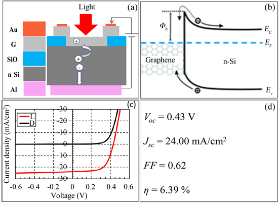
Schottky junction solar cell - Wikipedia In a basic Schottky-junction (Schottky-barrier) solar cell, an interface between a metal and a semiconductor provides the band bending necessary for charge separation. Traditional solar cells are composed of p-type and n-type semiconductor layers sandwiched together, forming the source of built-in voltage (a p-n junction). Due to differing energy levels between the Fermi level of the metal and ...
Energy Band Diagram - an overview | ScienceDirect Topics The Flat-Band Solar Cell: Energy Band Diagram The recipe for constructing the energy band diagram of a flat-band solar cell is outlined in Fig. 8, where the terminology of an eta-cell (a very thin p -type absorber on a TiO 2 sphere) is used.
Band diagram of the HIT solar cell based on n-type c-Si wafer in our ... The band diagram under thermal equilibrium of a-Si:H/c-Si heterostructure solar cell (no illumination) is sketched in Fig. 2. Due to the fact that the Fermi level is much closer to the...
Solar cell - Wikipedia A solar cell, or photovoltaic cell, ... From a solar cell to a PV system. Diagram of the possible components of a photovoltaic system. Assemblies of solar cells are used to make solar modules that generate electrical power from sunlight, as distinguished from a "solar thermal module" or "solar hot water panel". A solar array generates solar power using solar energy. Cells, …
A hole-conductor–free, fully printable mesoscopic perovskite solar cell ... 18.07.2014 · A schematic cross section of the triple-layer, perovskite-based, fully printable mesoscopic solar cell shows that the mesoporous layers of TiO 2 and ZrO 2 have thicknesses of ~1 and 2 μm, respectively, that were deposited on a F-doped SnO 2 (FTO) –covered glass sheet.The mesoporous layers were infiltrated with perovskite by drop-casting from solution …
Heterojunction Band Diagrams Explained - YouTube Heterojunctions are critical in virtually all modern optical electronics, as well as in the study of quantum mechanics, and in this video I describe how to draw their band diagrams. This is...
SOLAR CELL BAND DIAGRAMS AND POWER CURVES | Everything about solar energy These band edge diagrams show how a solar cell works. First, a photon is absorbed exciting an electron from the ground state or valence band in the P material to an excited conduction band state. It is mobile in the conduction band and if it lives long enough in this excited state, it can diffuse to the junction and fall down the potential barrier.
Multi-junction solar cell - Wikipedia Basics of solar cells [ edit] Figure A. Band diagram illustration of the photovoltaic effect. Photons give their energy to electrons in the depletion or quasi-neutral regions. These move from the valence band to the conduction band.
Please explain How to draw band bending diagram of IBC-SHJ solar cells ... The band diagram of IBC-SHJ is the same principle as the conventional solar cells. You don't have the choice : put the bulk on the middle, the n-contact on one side, and the p-contact on the other ...
Microsoft is building an Xbox mobile gaming store to take on … 19.10.2022 · Microsoft is quietly building an Xbox mobile platform and store. The $68.7 billion Activision Blizzard acquisition is key to Microsoft’s mobile gaming plans.
Multi-junction solar cell - Wikipedia Multi-junction (MJ) solar cells are solar cells with multiple p–n junctions made of different semiconductor materials.Each material's p-n junction will produce electric current in response to different wavelengths of light.The use of multiple semiconducting materials allows the absorbance of a broader range of wavelengths, improving the cell's sunlight to electrical energy conversion …
Band energy diagram of CdTe thin film solar cells - ScienceDirect The resulting band energy diagram is shown in Fig. 2 c. The valence band offset is 1.2 eV and the conduction band offset is approximately 0.1 eV. The difference of the conduction band minimum with respect to the Fermi level is 0.4 eV. Hence, 0.4 eV would occur as a loss in the photovoltage of the solar cell.
Learn Solar Energy | Band Gap Energy - YouTube In the last few videos, you've learned the working principle of a solar cell and the external parameters that define the performance of a solar cell. Now, yo...
Theory of solar cells - Wikipedia Band diagram of a solar cell, corresponding to very low current (horizontal Fermi level ), very low voltage (metal valence bands at same height), and therefore very low illumination Contents 1 Working explanation 2 Photogeneration of charge carriers 3 The p-n junction 4 Charge carrier separation 5 Connection to an external load
Understanding solar cell band diagram | Physics Forums The only thing that I can not completely understand is the physical operation of solar cell based on band diagram. Can anyone briefly explain the movements of carriers from one electrode to the another based on band diagram? Attachments IMG_20180311_202159_438.jpg 51.6 KB · Views: 1,191 IMG_20180311_202157_156.jpg 51.7 KB · Views: 1,340
Solar Cell Structure | PVEducation Solar Cell Structure. A solar cell is an electronic device which directly converts sunlight into electricity. Light shining on the solar cell produces both a current and a voltage to generate electric power. This process requires firstly, a material in which the absorption of light raises an electron to a higher energy state, and secondly, the ...











0 Response to "39 solar cell band diagram"
Post a Comment