40 consider the circuit in the diagram
Answered: Consider the circuit diagram in the… | bartleby Consider the circuit diagram in the figure. E1= 18 V 0.5 Q R 2.5 0 12 R, a 6.0 2 R 1.5 2 0.5 0 E2 = 45 V a) What is the equation which results when applying the loop rule to loop aedcba, in terms of the variables given in the figure? Circuit Diagram With Voltmeter - U Wiring Consider the circuit formed by network shown in figure. This circuit uses A2N3819 FET which provides a solid-state VOM. Voltmeter Electricity Meter And Electrical Circuit Sketch Stock Vector Image By Seamartini 92995988. Voltmeter Gauge Wiring Diagram. Circuit Diagram and Working Explanation.
Full Wave Rectifier-Bridge Rectifier-Circuit Diagram with ... In the circuit diagram, 4 diodes are arranged in the form of a bridge. The transformer secondary is connected to two diametrically opposite points of the bridge at points A & C. The load resistance R L is connected to bridge through points B and D. Full Wave Bridge Rectifier - Circuit Diagram with Input and Output Wave Forms

Consider the circuit in the diagram
Consider the circuit in the diagram, with sources of ... Consider the circuit in the diagram, with sources of emf listed below. Part (a) Find I1 in amps. Numeric : A numeric value is expected and not an expression. Part (b) Find I2 in amps. Numeric : A numeric value is expected and not an expression. Part (c) Find I3 in amps. Consider the circuit below. The bulb will light up if: Consider the circuit shown in the figure (a) Find the current i flowing through the circuit when the key K 1 is open and K 2 is closed (b) Find the net charge on the capacitor when K 1 is open and K 2 is closed and also when K 1 and K 2 both are closed. Consider the circuit diagram shown. Q. Consider the circuit diagram shown. Column I Column II; i: Potential difference across A and D in steady state is: p: 2 V: ii: Potential difference across capacitor in steady state is: q: 1.8 V: iii: Value of Q for which no energy is stored across capacitor is: r: 0.2 V: iv:
Consider the circuit in the diagram. Answered: Consider the circuit diagram depicted… | bartleby Consider the circuit diagram depicted in the fgure. It is known that two battery internal resistors r1and r2 are both 0.2Ω· = 12V and & = 24V. R2 16Ω 2. and Rs 262, but Ri is unknown. Caution: Current directions. › rl-sRL Series Circuit Analysis (Phasor Diagram, Examples ... Feb 24, 2012 · RL Circuit For drawing the phasor diagram of series RL circuit; follow the following steps: Step- I. In case of series RL circuit, resistor and inductor are connected in series, so current flowing in both the elements are same i.e I R = I L = I. So, take current phasor as reference and draw it on horizontal axis as shown in diagram. Step- II. Electric Circuit - Diagram, Symbol, Open and Closed ... Apr 28, 2020 · Study the circuit diagram and redraw it after making all corrections. View Answer Extra Question 12 - Draw a circuit diagram of an electric circuit containing a cell, a key, an ammeter, a resistor of 2 Ω in series with a combination of two resistors (4 Ω each) in parallel and a voltmeter across the parallel combination. Question with solution (circuit diagram) - My Electrical Note Solution: From the above circuit diagram we learn that it is a balanced bridge Because 2/3 = 2/3 and 3/6 = 3/6 LHS =RHS Therefore the middle resistance i.e, 2 Ω and 3Ω are open circuited and the resistances become in series as follows: Now the above circuit diagram can be simplified as follows:
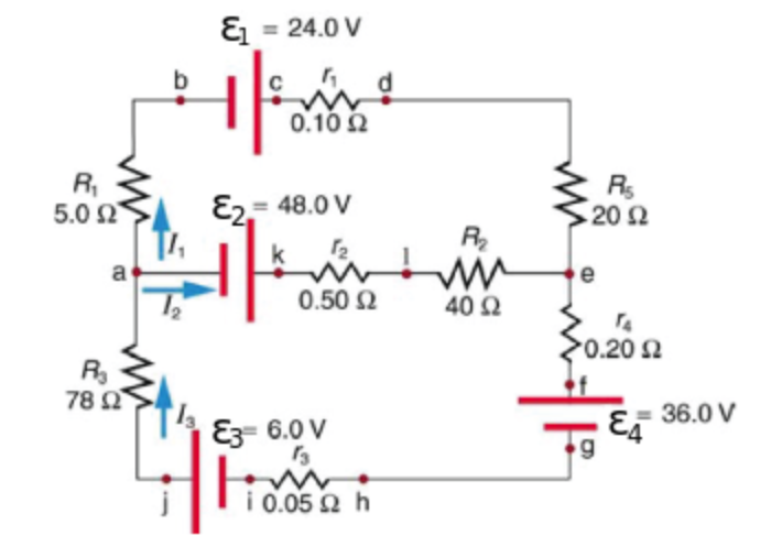
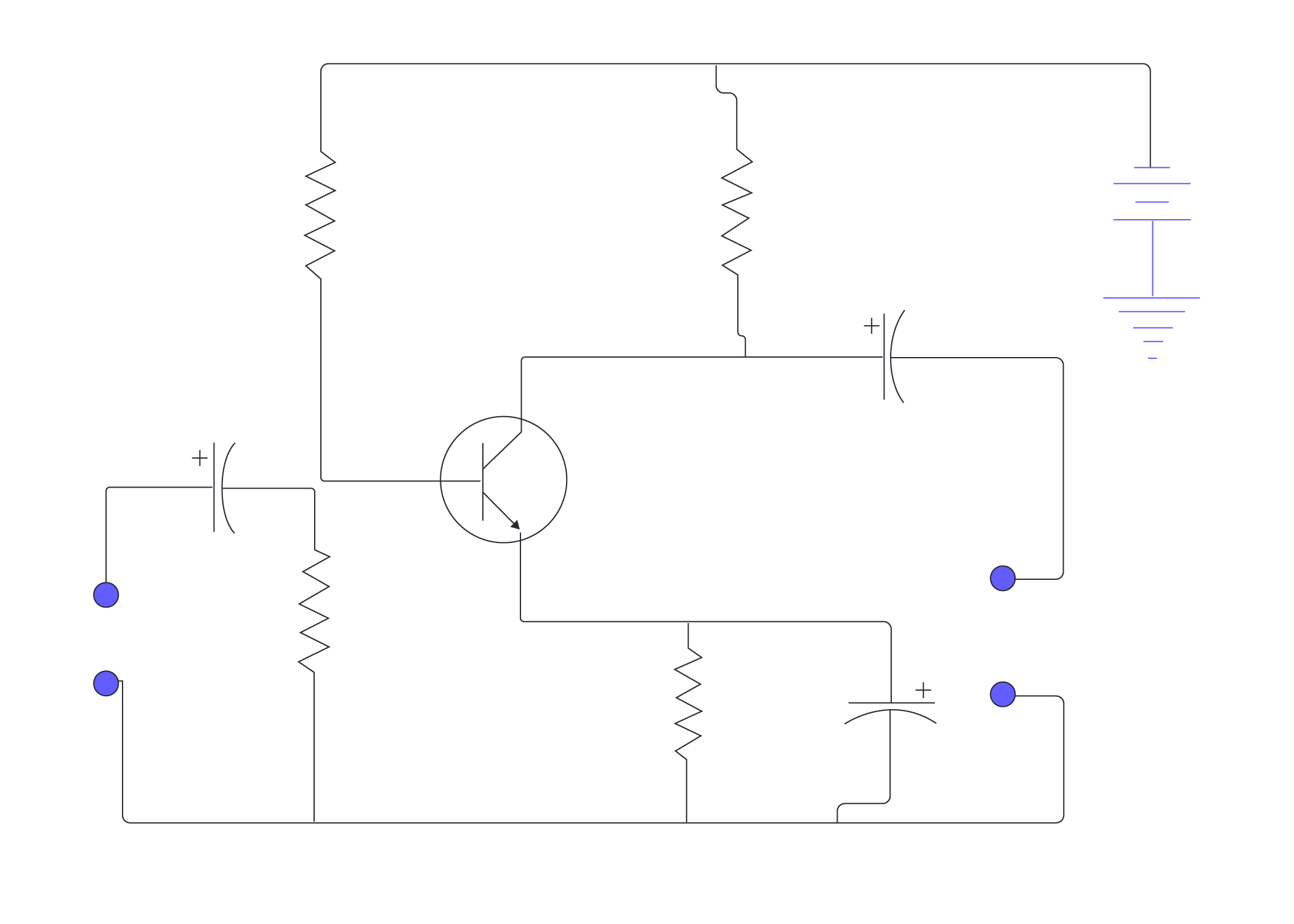
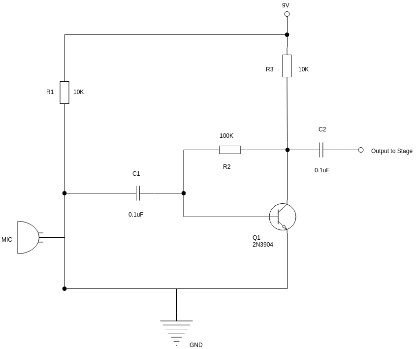
How to make a Supercapacitor Charger Circuit 29.5.2019 · The complete circuit diagram for this Supercapacitor Charger Circuit is given below. The circuit was drawn using Proteus software the simulation of the same will be shown later. The circuit is powered by a 12V adapter; we then … Common Emitter Amplifier : Circuit Diagram, Working & Its ... Working of Common Emitter Amplifier. The below circuit diagram shows the working of the common emitter amplifier circuit and it consists of voltage divider biasing, used to supply the base bias voltage as per the necessity. The voltage divider biasing has a potential divider with two resistors are connected in a way that the midpoint is used for supplying base bias voltage. Consider the following circuit diagram - YouTube Consider the following circuit diagram. (a) Find the current flowing through the 5 Ω resistor. (b) Find the potential difference across the 3 Ω resistor. (c)... Consider the circuit in the diagram, with ... | Clutch Prep Consider the circuit in the diagram, with sources of emf listed below. Randomized Variables. ℰ1 = 21 V. ℰ2 = 49 V. ℰ3 = 9.5 V. ℰ4 = 39 V. a) Find I 1 in amps. B) Find I 2 in amps. C) Find I 3 in amps.
Consider the following circuit diagram. If R1 = R2 = R3 ... Click here👆to get an answer to your question ️ Consider the following circuit diagram. If R1 = R2 = R3 = R4 = R5 = 3Ω the equivalent resistance of the circuit is circuitdigest.com › electronic-circuits › cell-phoneCell Phone Charger Circuit Diagram Aug 11, 2015 · Mobile phones generally charge with 5v regulated DC supply, so basically we are going to build a circuit diagram for 5v regulated DC supply from 220 AC. This DC supply can be used to charge mobiles as well as the power source for digital circuits, breadboard circuits, ICs, microcontrollers etc. Physics Tutorial: Combination Circuits Consider the combination circuit in the diagram at the right. Use the diagram to answer the following questions. (Assume that the voltage drops in the wires themselves in negligibly small.) PDF Circuit Circuit Circuit Analysis with Answers In the circuit diagram below, two 4-ohm resistors are connected to a 16-volt battery as shown. 4.0 Q 16 V 4.0 The rate at which electrical energy is expended in this circuit is 1. 8.ow 2. 16 w 3. 32W 4. 64 W TWO identical resistors connected in series have an equivalent resistance of 4 ohms. The same two resis-
Consider the following circuit diagram. If R1 = R2 = R3 = R4 ...
Infrared Motion Detector Circuit - Circuit Diagram ... Circuit Diagram For Motion Detector Circuit. Infrared Motion Detector Circuit. The bulb in the circuit can be replaced with any of the home appliances which works on 230V AC. ... Please consider supporting us by disabling your ad blocker.
Solved Consider the circuit depicted in the diagram. If the ...
Multi-loop Circuits and Kirchoff's Rules - Boston University Consider the circuit below: ... On a circuit diagram, an ammeter is shown as an A in a circle. Again, the ammeter acts as a resistor, so to minimize its impact on the circuit it must have a small resistance relative to the resistance of the resitor whose current is being measured.
Circuit Diagram Maker | Lucidchart
2 Bit Comparator Circuit Diagram - U Wiring The truth table and logic circuit for a 1-bit comparator are given below. 11 shows the block diagram of a two-bit comparator which has four inputs and three outputs. 2-Bit Comparator- A 2-bit comparator compares two binary numbers each of two bits and produces their relation such as one number is equal or greater than or less than the other.

Consider the circuit diagram depicted in the figure
Kirchhoff's Rules | Physics - Lumen Learning The diagram shows an example of Kirchhoff's first rule where the sum of the currents into a junction equals the sum of the currents out of a junction. In this case, the current going into the junction splits and comes out as two currents, so that I1 = I2 + I3. Here I1 must be 11 A, since I2 is 7 A and I3 is 4 A. Kirchhoff's Second Rule
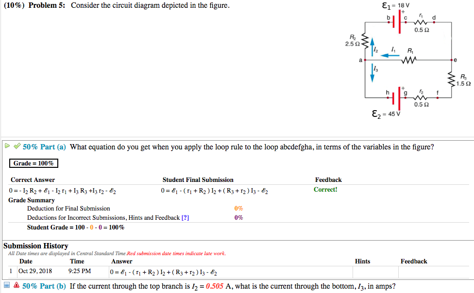
Solved (10%) Problem 5: Consider the circuit diagram | Chegg.com
Consider the circuit in the diagram, with sources of ... Transcribed image text: Consider the circuit in the diagram, with sources of emf listed below. EL b . 0.100 RS Randomized Variables &1 = 21 V 82 = 49 V 83 = 11.5 V 84 = 48 V R 5.0 ΩΣ TH E2 2002 a R w 40Ω e 0.502 that >0.2022 78ΩΣ (E3 EL 9 DA 33% Part (a) Find 1, in amps. 1,= 1 JT ( 7 8 9 HOME E 4 5 6 sino cos tan cotan asino acos atan acotan sinh cosh tanho cotanh Degrees Radians 3 * 1 2 ...

Consider the circuit diagram depicted in the figure
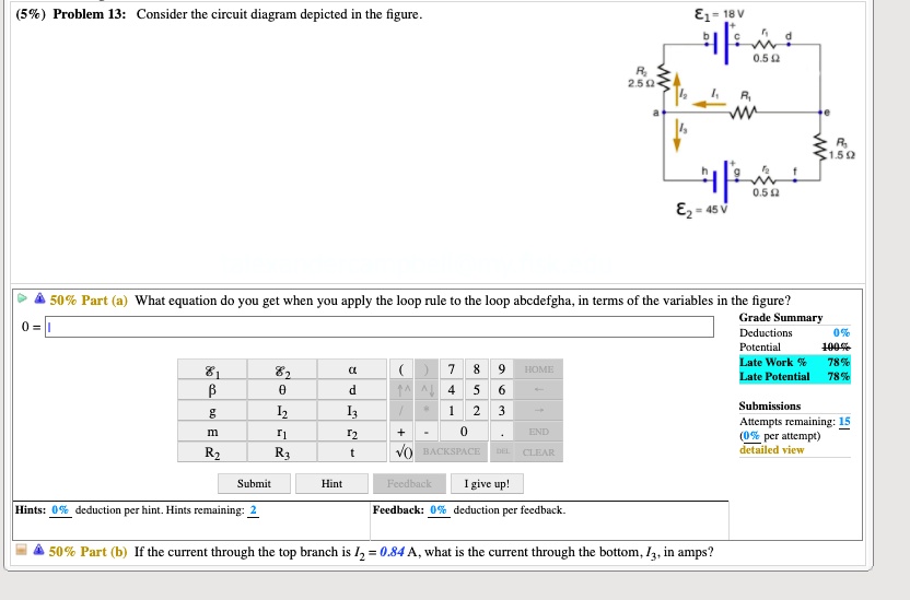
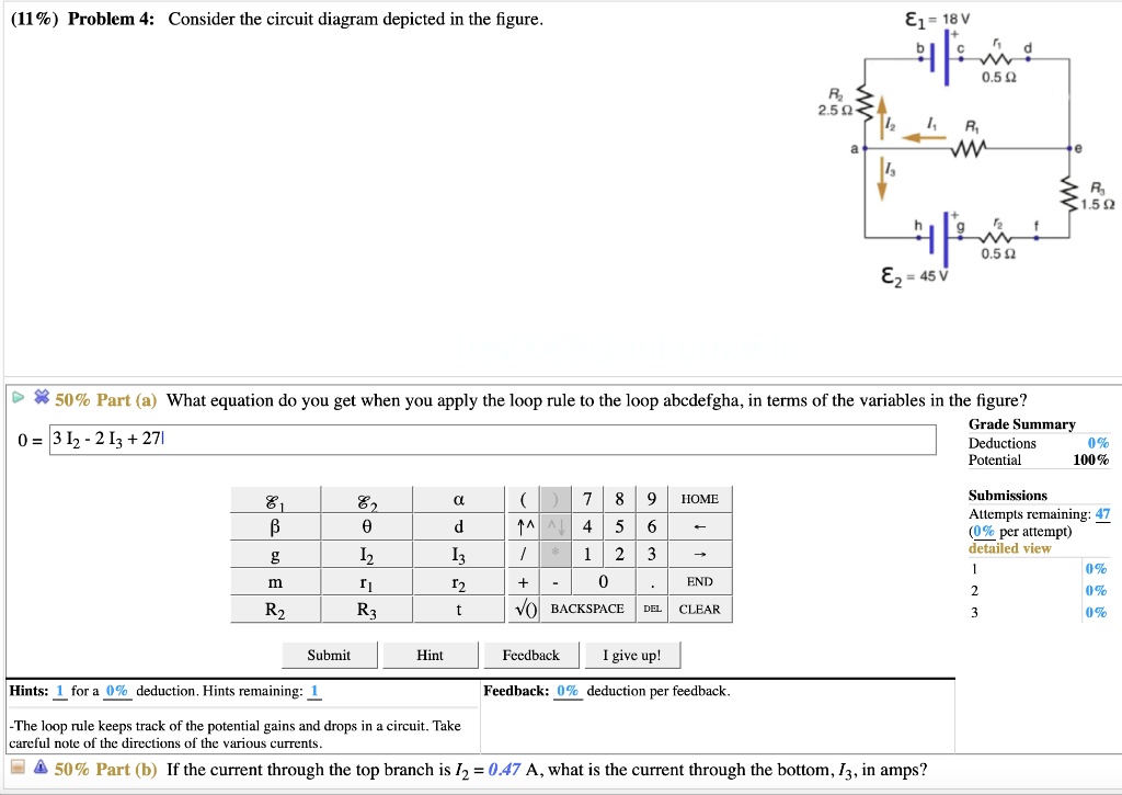
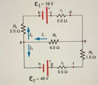
Consider the circuit diagram depicted in t... | Clutch Prep Problem Details. Consider the circuit diagram depicted in the figure. Part (a) What equation do you get when you apply the loop rule to the loop abcdefgha? Part (b) If the current through the top branch is I2 = 0.49 A, what is the current through the bottom I3, in amps? Learn this topic by watching Kirchhoff's Loop Rule Concept Videos.
Circuit Diagram And Its Components - Explanation With Circuit ...
Inverter Circuit Diagram: A Complete Tutorial | EdrawMax Steps to Make an Inverter Circuit Diagram This section will tell you about how to make a simple 100-watt inverter circuit diagram. In the home or industries scenarios, you normally purchase it from the market, but when you have to make it with your hands for project purposes, you can follow these steps accurately.
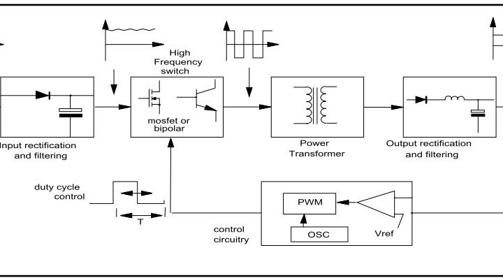
lab.cvič. 12 - Usměrňovače
PDF PHYS-2020: General Physics II Course Lecture Notes Section IV Example IV-1. Consider the circuit shown below, where R1 = 3.00 Ω, R2 = 10.0 Ω, R3 = 5.00 Ω, R4 = 4.00 Ω, and R5 = 3.00 Ω. (a) Find the equivalent resistance of this circuit. (b) If the total power supplied to the circuit is 4.00 W, find the emf of the battery. + − E R1 R2 R3 R4 R5 Solution (a): We have to reduce this circuit in steps ...

Colpitts Oscillator Tutorial and Colpitts Design
Consider the circuit shown in the figure. The current I3 ... Solution. Verified by Toppr. Correct option is D) Suppose current through different paths of the circuit is as follows. After applying KVL, for loop (1) and (2) We get 28i 1. . =−6−8⇒i 1. .
switched-mode : The Talema Group
[Solved] Consider the circuit diagram in the figure. a ... Consider the circuit diagram in the figure. a) What is the equation which results when applying the loop rule to loop aedcba, in terms of the variables given in the figure? Image transcription text (17%) Problem 2; Consider the circuit diagram in the figure. E1 = 18V 0.5 0 2.5 0 M 6.0 12 0.5 12 E, - 45 V Ctheexpertta.com @theexpertla.com ...
SOLVED:%c) Problem 13: Consider the circuit diagram depicted ...
RLC Series circuit, phasor diagram with solved problem 27.9.2018 · RLC Series circuit contains a resistor, capacitor, and inductor in series combination across an alternating current source. The behavior of components can be explained by phasor diagrams, impedance and voltage triangles.

Speed sensor | Bosch Rexroth Česká republika
Answered: Consider the circuit diagram below. The… | bartleby Consider the circuit diagram below. The voltage across R, is 6.8 V with the polarity shown. Calculate the current through R5 without using node analysis, mesh analysis or superposition.
Arithmetic Circuits
xkcd.com › 730Circuit Diagram - xkcd This work is licensed under a Creative Commons Attribution-NonCommercial 2.5 License. This means you're free to copy and share these comics (but not to sell them). More details.
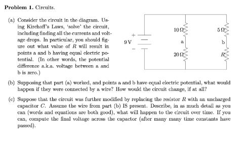
Solved Problem 1. Circuits. 105 9V (n) Consider the circuit ...
DOC QUESTION 1 - Physical Sciences Break 1.0 Consider the diagram of a circuit containing one cell connected to 2 bulbs in series with a switch that is closed. 4.1 Copy the diagram onto your answer sheet and draw in an ammeter that measures the current through the wire at A. (1) 4.2 The current at A was found to be 0,6 A. What is the current at point C?

Consider the following circuit diagram. If R1 = R2 = R3 = R4 ...
Answered: Consider the circuit in the following… | bartleby Consider the circuit in the following diagram, where the resistances are R1 = 0.15R, R2 = 2R, R3 = 0.55R, and R4 = 3R, where R = 78 Ω. The circuit is connected to a V = 4.7 V source. (i) Input an expression for the equivalent resistance of the circuit in terms of R1, R2, R3, and R4.

Consider the circuit shown in the diagram below. The battery ...
Transistor As Amplifier - Working, Circuit Diagram, Common ... If we consider ∆V 0 and ∆V i as small changes in output and input voltages respectively, then ∆V 0 / ∆V i is called as the small-signal voltage gain, A v of the amplifier. Therefore, ∆V 0 = 0 – R c ∆I C. The gain in terms of voltage when the changes in input and output currents are observed is called Voltage gain. Similarly in ...

Circuit diagram - Wikipedia
Answered: ENL Consider the circuit diagram… | bartleby ENL Consider the circuit diagram depicted in the figure. E- 18 V 0.50 250 ww 1.50 0.50 (a) What equation do you get when you apply the loop rule to the loop abedefgha, in terms of the variables in the figure? (b) If the current through the top branch is /037 A, what is the current through the bottom, I, in amps? sin tan.

Consider the circuit in the diagram, with sources of emf ...
› rl-circuit-derivationRL Circuit : Derivation, Response Factors, Phasor Diagram and ... Jul 23, 2021 · To draw a phasor diagram for the circuit, below are the steps to be followed. Consider, the current ‘I’ as a reference point; The voltage drop that takes place across resistor V R = I R is drawn in the exact phase with that of current ‘I’.

Consider the circuit diagram depicted in the figure. a. What ...
Solved > Question Consider the circuit diagram depicted in ... Question. Consider the circuit diagram depicted in the figure. What equation do you get when you apply the loop rule to the loop abcdefgha, in terms of the variables in the figure? 0 = If the current through the top branch is I_2 = 0.69 A, what is the current through the bottom, I_3, in amps?

The attached circuit diagram shows connection of 3 resistors ...
consider the circuit shown in the diagram find the current ... consider the circuit shown in the diagram find the current in 3 Ω resistor - Physics - TopperLearning.com | ij7jct7kk. Starting early can help you score better! Avail 25% off on study pack. Avail Offer.
SOLVED:%) Problem 4: Consider the circuit diagram depicted in ...
Consider the circuit diagram shown. Q. Consider the circuit diagram shown. Column I Column II; i: Potential difference across A and D in steady state is: p: 2 V: ii: Potential difference across capacitor in steady state is: q: 1.8 V: iii: Value of Q for which no energy is stored across capacitor is: r: 0.2 V: iv:
Logiciel de schéma de circuit
Consider the circuit below. The bulb will light up if: Consider the circuit shown in the figure (a) Find the current i flowing through the circuit when the key K 1 is open and K 2 is closed (b) Find the net charge on the capacitor when K 1 is open and K 2 is closed and also when K 1 and K 2 both are closed.

Resistors in Parallel: Circuit Analysis with Parallel ...
Consider the circuit in the diagram, with sources of ... Consider the circuit in the diagram, with sources of emf listed below. Part (a) Find I1 in amps. Numeric : A numeric value is expected and not an expression. Part (b) Find I2 in amps. Numeric : A numeric value is expected and not an expression. Part (c) Find I3 in amps.
Physics Tutorial: Combination Circuits

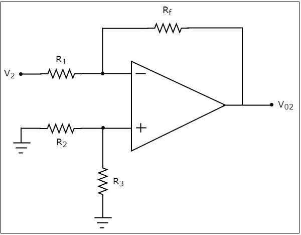
Op Amp Circuit | Electrical4U

787-2861/108-020

Consider circuit as shown in figure. The current through wire ...

Consider the circuit diagram as given below. If R1=R2=R3=R4 ...

Consider the circuit diagram as given below. If R1=R2=R3=R4 ...
Answered: Consider the circuit diagram in the… | bartleby
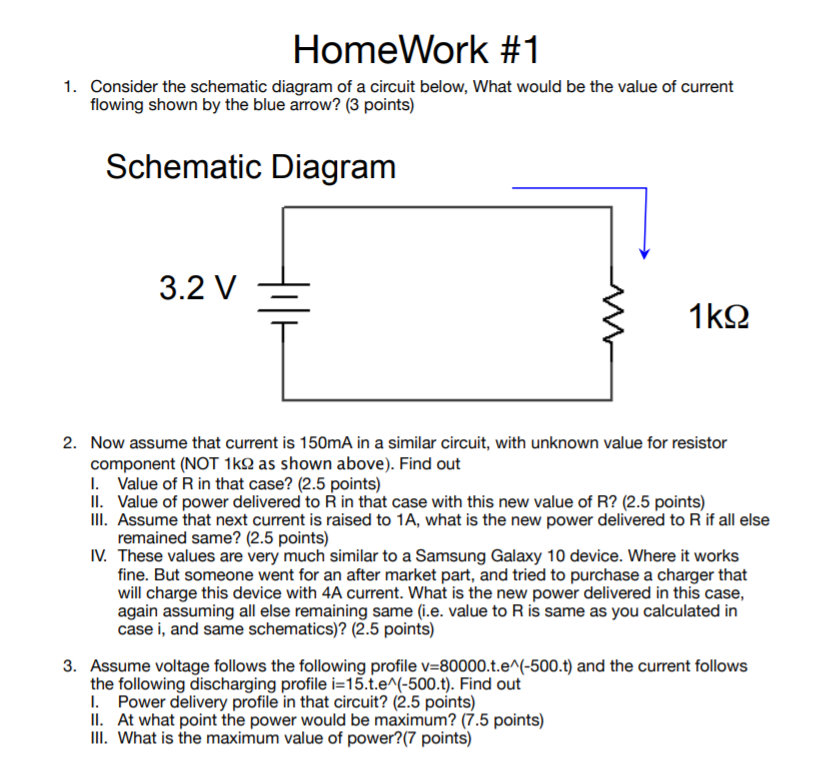
Solved HomeWork #1 1. Consider the schematic diagram of a ...
An Introduction to Ground: Earth Ground, Common Ground ...
Solved: Consider the circuit in the diagram, (a) Draw the ...
Solved Consider the circuit diagram. Use Kirchhoff's rules ...
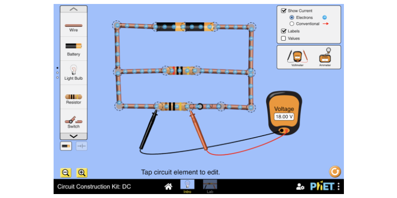
Stavebnice obvodů: DC - Sériové zapojení, Paralelní zapojení ...
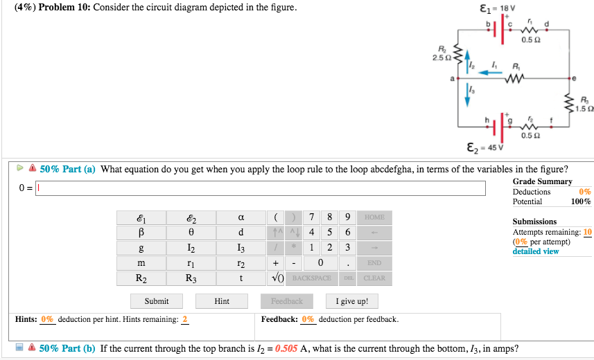
Solved (4%) Problem 10: Consider the circuit diagram | Chegg.com
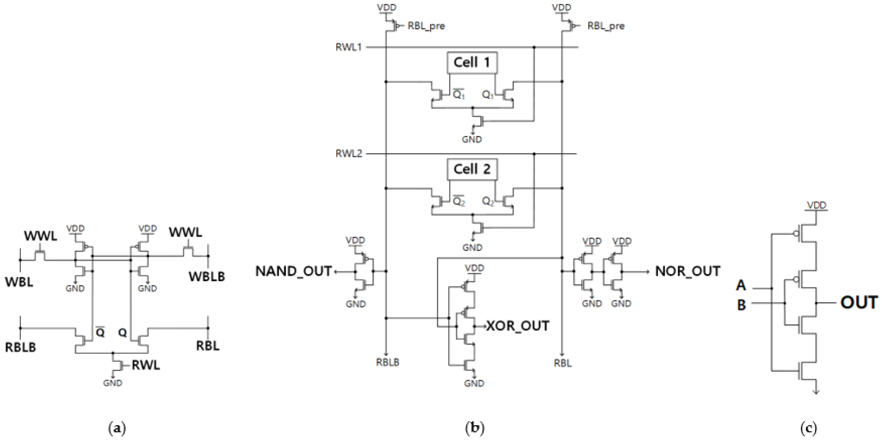
Electronics | Free Full-Text | Novel In-Memory Computing ...

Consider the circuit in the diagram, with sources of emf ...

consider the following circuit diagram. If R1=R2=R3=R4=R5 ...
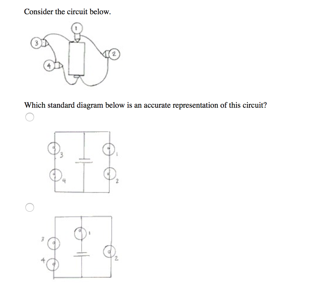
Solved Consider the circuit below. 2 Which standard diagram ...
0 Response to "40 consider the circuit in the diagram"
Post a Comment