39 vdo tachometer wiring diagram
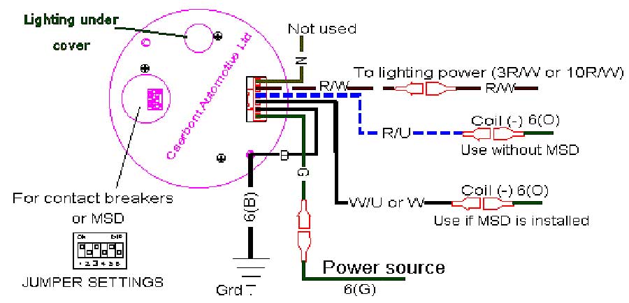
marjonklomps.nl › ford-gauge-cluster-problemsmarjonklomps.nl Mar 16, 2022 · Texas Instrument Cluster We fix 2003-2006 GM Instrument Clusters,Speedometer,Tachometer,Gauges Repaired. Totally Rebuilt To Look & Work Like New! Call (989) 839-4877 if your Cluster is Not Listed. To test the temperature gauge and wiring, you can simulate a sensor signal at the sensor connector. back to all those items. PDF Viewline Instrument Kit Installation ... - vdo-gauges.com 3. Mount the gauge and secure with the VDO Spin-Lok™ Clamp. See page 14-15 for mounting options and instructions. Wiring the Gauge (Illustration D): 1. See page 12-13 for wire harness hookup: b) Tachometer signal source to the purple lead wire. Signal source can be: the Ignition Coil (negative terminal), Alternator W terminal, Inductive ,
Vdo Tachometer Wiring Diagram Vdo Tachometer Wiring Diagram. Refer to Diagram B for dimensions. shown in Diagram C. You may also mount the tachometer the installation, wiring, calibration and operation of all. VDO. Wire the tachometer to the vehicle as shown in Diagram H on Page 4. Please understand that proper wiring must be maintained throughout your vehicle.

Vdo tachometer wiring diagram
Tachometer Wiring Diagram - Wiring Diagram Vdo Marine Tachometer Wiring Diagram - Data Wiring Diagram Schematic - Tachometer Wiring Diagram Wiring Diagram contains several detailed illustrations that present the relationship of varied things. It consists of guidelines and diagrams for various types of wiring techniques as well as other items like lights, home windows, etc. Vdo Tachometer Wiring Diagram - justussocializing.org Vdo Tachometer Wiring Diagram- One of the most hard automotive fix tasks that a mechanic or fix shop can bow to is the wiring, or rewiring of a car's electrical system.The hardship in fact is that every car is different. in imitation of grating to remove, replace or repair the wiring in an automobile, having an accurate and detailed Vdo Tachometer Wiring Diagram is critical to the ... PDF Tachometer Installation and Operation Instructions Install them now. Refer to Diagram E. 12. Connect the black wire from the tachometer to the black wire of the shielded cable (GROUND). 13. Connect the green wire from the tachometer to the white wire in the shielded cable (TACH SIGNAL). 14. Finally, connect the red wire from the tachometer to the red wire in the shielded cable. The remaining white
Vdo tachometer wiring diagram. › category › did-you-knowDid You Know? Archives - Hollywood.com Click to get the latest Did You Know? content. Vdo Gauges Wiring Diagram Vdo Gauges Wiring Diagram. The VDO Programmable Speedometer featured in this installation Refer to diagram B below for the sender wiring for a hall- wiring more than one gauge. VDO cockpit vision VDO cockpit international. Published by: . steel, zinc-plated and chromatized (ammeter, turbocharger gauge) . Volvo Penta Tachometer Wiring Diagram - IOT Wiring Diagram IOT Wiring Diagram. 873998 23715874 Volvo Penta Tachometer 3400rpm. 21628160 volvo penta evc tachometer 4000rpm 23715875 was tamd40a tacho cruisers installation and operations wiring diagram disappointment tach needle pegs with engine hallberg rassy 31 monsun electrical system 30 general component location of tad734ge d ips gauge for mercruiser 383 boat user manual ab car motormanagement ... Tachograph Fitting Instructions - Riayk Ltd Vdo Tachograph ... vdo tacho meters. vdo gauges (1) vehicle / model. manufacture (209) manufacture (209) alexander dennis tachographs (3) autosan tachographs (2) citroen tachographs (5) daf tachographs (20) dennis eagle tachograph (4) erf tachographs (14) evobus tachographs (6) fiat tachographs (6)
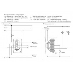
VDO Installation and Troubleshooting Guides ... If you have additional questions please contact VDO: Aftermarket Technical Support & Troubleshooting. autotechsupport@vdo.com. Repair & Service for Aftermarket Gauges and Accessories Connie Heflin Phone: 540-678-2034 Fax: 540-662-2515 cheflin@vdo.com. Repair & Service for OEM Instrument Clusters and Systems Merri MCIntyre Phone: 540-665-2446 PDF INSTALLATION INSTRUCTIONS: Viewline 85 mm - VDO Tachometer, without Display 13 GB 14 Connector set, 8-pin A2C59510850 30 - terminal 30 - steady-state plus 12 V 15 - terminal 15 - connected (ignition) plus 58 - terminal 58 - lighting 31 - terminal 31 - ground Designations in the wiring diagram: 8-pin connection F1 - fuse 5A quick-response C1 - 8-pin MQS connector You must comply with the wiring diagram. PDF 0 515 010 482 -- Xtreme Tachometer • VDO does not recommend mounting your Xtreme 3. Wiring the Tachometer • Turn off the ignition and disconnect the negative terminal from the battery post if you haven™t already done so. • Wire the tachometer to the vehicle as shown in either Diagram C * or Diagram D *. * Refer to your vehicle™s owner/service manual or the Vdo Gauges Wiring Diagram - schematron.org Description: Vdo Gauges Wiring Diagrams And Boat Tach Diagram E Z Go Golf Cart for Boat Gauge Wiring Diagram For Tachometer, image size X px, and to view image details please click the image. Here is a picture gallery about Boat Gauge Wiring Diagram For Tachometer complete with the description of the image, please find the image you need.
VDO Documentation - VDO Marine Gauges VDO Resitive Gauge wiring Instructions - 2009; Veratron Flex Gauge 52mm NMEA2000 12/24v; ViewLine 52mm Wiring Diagram (2014) Viewline Level Gauges 12/24 Volt (2011) Viewline Level Gauges 52mm (2008) Viewline Pitot Speedometer / Level Gauge (2011) Viewline Pitot Speedometer/Fuel Gauge 110mm (2011) Viewline Pitot Speedometer/Fuel Gauge 110mm (2013) VDO TACHOMETER Installation manual - manualzilla.com Reattach the mounting cup, then mount the keypad in the location of your choice. III. Wiring the Tachometer 1. Remove the key from the ignition and disconnect the negative terminal from the battery post. 2. Wire the tachometer to the vehicle as shown in Diagram H on Page 4. Please understand that proper wiring must be maintained throughout your vehicle. PDF INSTALLATION INSTRUCTIONS 5 Tachometer 7. Wire installations should be neat and tied down to prevent tugging and fraying of wires at connections. Trouble Shooting if your tach does not function properly after installation check the following: 1. Are all electrical connections correct and tight? 2. if neither tach nor dial light work, check ground and 12V power connections. 3. Vdo Voltmeter Wiring Diagram Sep 06, · VDO guages I bought don t work img source: diagramweb.net Stewart Warner Voltmeter Wiring Diagram installation instructions re mended panel cutout hole how to install your instrument s contact your local stewart warner distributor or contact our technical support team toll voltmeter wiring figure 5.
Unterwasserbeleuchtung für Boot - Apelo A2 - Hella Marine ...
› engine-gaugesEngine Gauges - Wholesale Marine Boat Gauges. Marine gauges are usually console-mounted to allow boaters an overview of the operations at a glance. Each boat gauges indicates an important boating function such as travelling speed, engine temperature, the number of operating hours, the water depth, fuel level, wind speed, water temperature, oil pressure and the amount of electricity being generated.
TheSamba.com :: VDO Tachometer
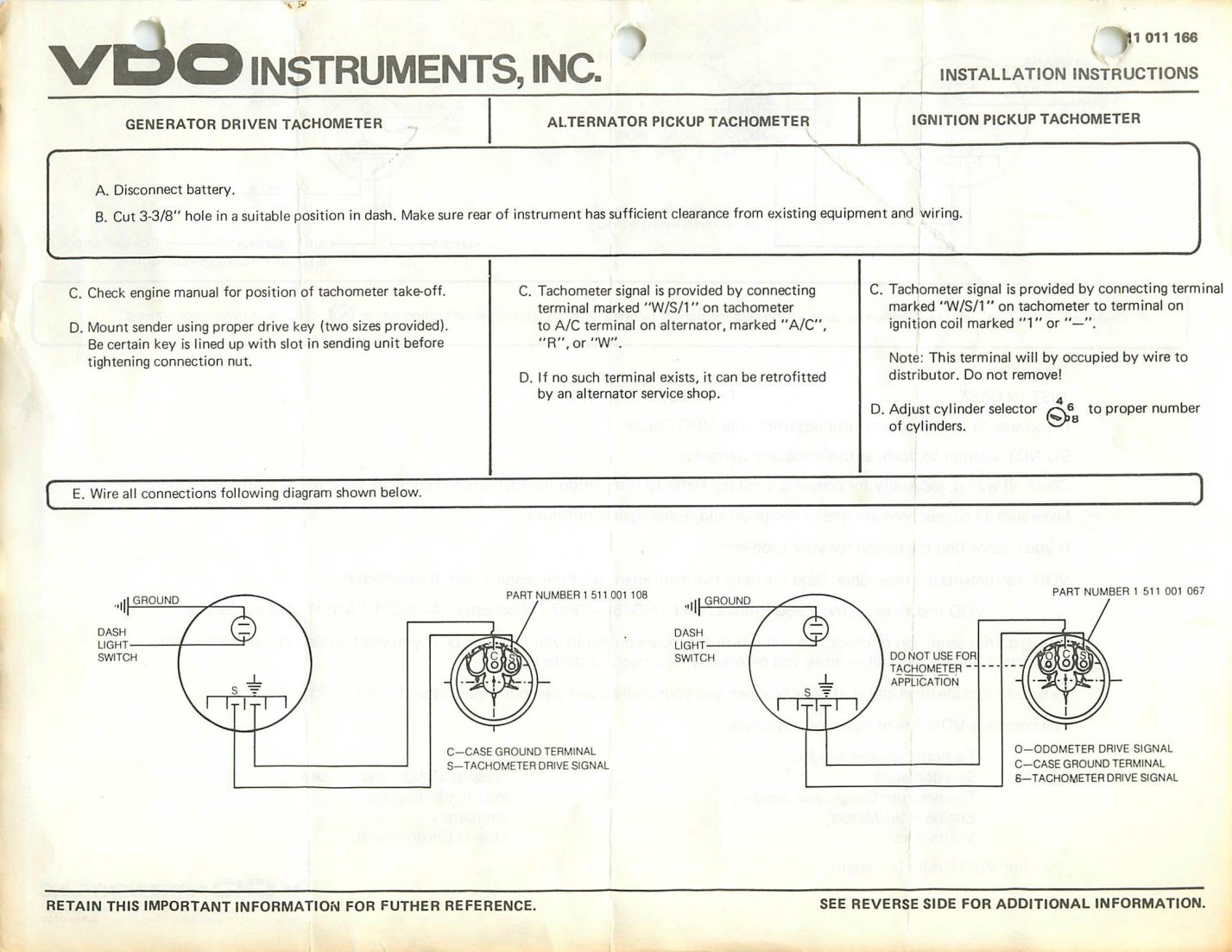
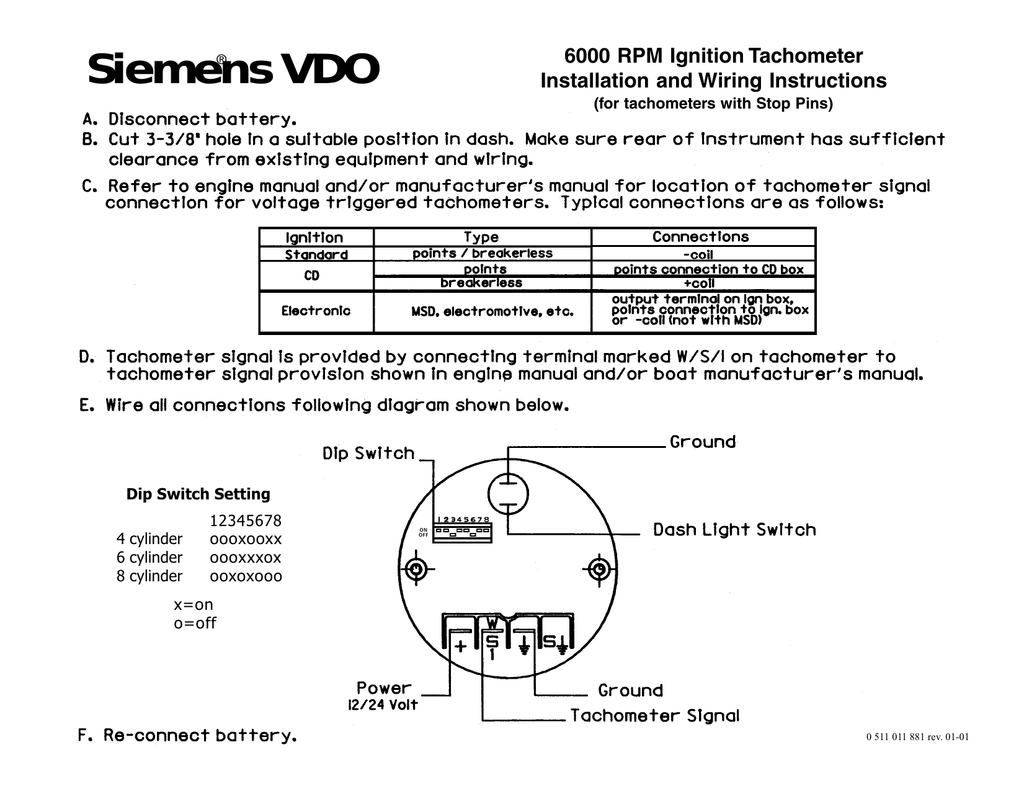
PDF Siemens ® VDO - Summit Racing Equipment check your wiring, referring to the wiring description in Diagram C. d) the location of the signal source (alternator, coil or other ignition signal source). 2. Connect the wiring to the appropriate tachometer terminals as shown in Diagram C. Configuring the T achometer: Before your VDO Tachometer will func-tion properly with your engine, you will

Manuals for VDO Equipment - MARINE DIESEL BASICS
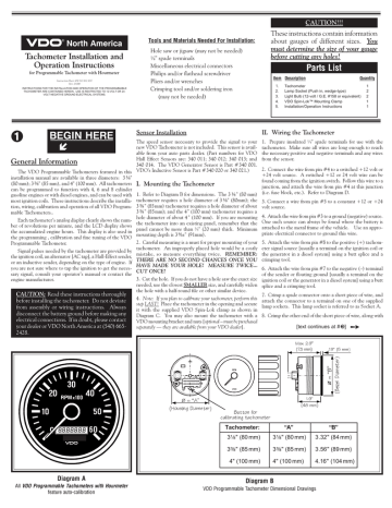
PDF Tachometer Installation and before ... - VDO Instruments Diagram A VDO Tachometer with Hourmeter is programmable from .5 to 200 pulses per revolution VDO VDO Item Description Quantity 1. Tachometer 1 2. Lamp Socket (Push in, wedge-type) 2 3. Light Bulb (12-volt / G.E. #161 or equivalent) 2 4. VDO Spin-Lok™ Mounting Clamp 1 5. Installation/Operation Instructions 1 Parts List These instructions ...

Tachometer - VDO Instruments and Accessories
Vdo Marine Tachometer Wiring Diagram - Data Wiring Diagram ... Tachometer Wiring Diagram - boat tachometer wiring diagram, bosch tachometer wiring diagram, defi tachometer wiring diagram, Every electrical arrangement is composed of various distinct pieces. Each component ought to be placed and connected with other parts in particular manner. If not, the arrangement will not function as it should be.

VDO Tacho
PDF ˇ ˘ˇˆ - VDO Instruments and Accessories Diagram E Proper wiring of the VDO Programmable Tachometer with typical ignition systems ˘ˇˆ ˙˘ ˝ˇ ! "˙ Diagram F Fine adjustment of the VDO Tachometer when used with an alternator Compare the VDO Tachometer reading with that of a reference tachometer. Adjust the potentiometer on the back of the tach. When the VDO Tachometer reading

VDO TACHOMETER Installation manual | Manualzz
alexander-goers.de › toyota-ecu-resetPage Not Found AE111 Air conditioning electrical system *Part 2*. Oct 18, 2011 · Facelift headlight wiring diagram. Jan 04, 2021 · Smart Code Reset fails when all keys are lost. Note that this method is almost foolproof as long as all ECU control parameters are still within their normal ranges. That will drain down the capacitors that hold history and settings.
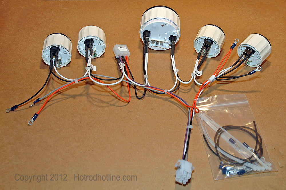
Updating To An Electrical Gauge Package | Hotrod Hotline
PDF VDO Tachometer Installation Instructions Page 1 of 4 plan to calibrate your tachometer, skip Step 3 and return after calibration is completed. 3. Place the tachometer in the opening and secure with the VDO Spin-Lok clamp provided (see diagram B). You may also mount the tachometer with a VDO mounting bracket and nuts (purchased separately). Diagram B Dash Panel 3/4" [20mm] maximum thickness Dash Panel
smithsclassic
PDF For Ducati & Rotax VDO - VDO Instruments Use a wrench to tighten the nuts until the tachometer can not longer be rotated by hand. DO NOT OVERTIGHTEN. See Diagram C. Wiring the Tachometer: iring your new VDO Tachometer is a simple and straightforward procedure, as shown in Diagram D. al, or the spot where the negative battery fuse box); and
Tachometer Installation and Operations Instructions
Vdo Diesel Tachometer Wiring Diagram - schematron.org Vdo Diesel Tachometer Wiring Diagram For ducati & rotax vdo vdo instruments and accessories, before your vdo tachometer will function properly with your engine, you will need to configure it as shown in diagram e the table in diagram e shows how to set the dip . VDO Tachometer is not included. This sensor is avail-able from your auto parts dealer.
TAS AUTOMOTIVE :: AUTO ELECTRICAL CAMERAS
PDF VDO Installation Guide - cbperformance.net Tachometer Back of Tachometer Light Switch Light Switch Ignition Battery Battery Fuse Block Fuse Block (Switched +12v) Ignition (Switched +12v) Red Sensor Wire to Pin #2 Off-White to Pins #6 & #8 Black Sensor Wire Hall-Effect Sensor 1715 N Farmersville Blvd., Farmersville, CA 93223 info@cbperformance.com 1-800-274-8337 cbperformance.com Proper ...

Oceanlink Master Tachometer / 7000 RPM / 85 mm / white only ...
4 In 1 Tachometer Wiring Diagram - easywiring Here is how to wire the chinese digital tachometer. The yellow wire from our tachometer can receive signal from the ecu by following the diagram in fig 4. Diagram a vdo tachometer with hourmeter is programmable from 5 to 200 pulses per revolution vdo vdo item description quantity 1. Variety of autometer tach wiring diagram.

How To install a Tach that has 5 wires | Mindustries
Rpm Tachometer Wiring Diagram - Studying Diagrams Rpm tachometer wiring diagram. Tachometer 561 hourmeter 0-3000 RPM Electrical 12 24 volts Diagram D Proper wiring of the tachometer with. This sensor is avail-able from your auto parts dealer. To install the light bulbs use needle nose pliers to insert the bulb in the bulb receptacle on back of gauge then twist clockwise ¼ turn to lock into ...

EcoDim ECO-DIM.07 WIFI Universal WiFi LED dimmer RLC User ...
Boat Gauge Wiring Diagram For Tachometer | Fuse Box And ... Description: Vdo Gauges Wiring Diagrams And Boat Tach Diagram E Z Go Golf Cart for Boat Gauge Wiring Diagram For Tachometer, image size 1200 X 1362 px, and to view image details please click the image. Here is a picture gallery about Boat Gauge Wiring Diagram For Tachometer complete with the description of the image, please find the image you need.

Bouncey Tach - Page 2 - Pelican Parts Forums
Vdo Volt Gauge Wiring Diagram - easywiring Vdo volt gauge wiring diagram. Connect the harness according to the following wiring matrix. If using the warning led in the gauge and a vdo sender with warning contact wk see wiring information in illustration a 3.

Tachometer Wiring diagram Electrical Wires & Cable Car, car ...
" Old "VDO tacho diagram. - AULRO.com I have the wiring/dip switch diagram for 333 351 and 333 354 tacho's. I can scan it if it's the right one. I tried it in my 300Tdi (it's out of my old race car) but still reads high, even after adjusting the internal pot. Hi, after searching for info on my old VDO tacho, I found your post here.
0 515 012 020 -- Programmable Tachs without hourmeters -- rev ...
PDF Tachometer Installation and Operation Instructions Install them now. Refer to Diagram E. 12. Connect the black wire from the tachometer to the black wire of the shielded cable (GROUND). 13. Connect the green wire from the tachometer to the white wire in the shielded cable (TACH SIGNAL). 14. Finally, connect the red wire from the tachometer to the red wire in the shielded cable. The remaining white

VDO Viewline Tachometer 4000 RPM - 85mm - Black Dial
Vdo Tachometer Wiring Diagram - justussocializing.org Vdo Tachometer Wiring Diagram- One of the most hard automotive fix tasks that a mechanic or fix shop can bow to is the wiring, or rewiring of a car's electrical system.The hardship in fact is that every car is different. in imitation of grating to remove, replace or repair the wiring in an automobile, having an accurate and detailed Vdo Tachometer Wiring Diagram is critical to the ...
tachometer wiring puzzle.... | SailNet Community
Tachometer Wiring Diagram - Wiring Diagram Vdo Marine Tachometer Wiring Diagram - Data Wiring Diagram Schematic - Tachometer Wiring Diagram Wiring Diagram contains several detailed illustrations that present the relationship of varied things. It consists of guidelines and diagrams for various types of wiring techniques as well as other items like lights, home windows, etc.
INSTALLATION INSTRUCTIONS: Viewline 52 mm
0 511 011 881a -- 6000 RPM Ignition Tachometer | Manualzz

Siemens® VDO - Vehicle Controls | Manualzz

VDO Tachometer Kit (80mm, 0–7000rpm)
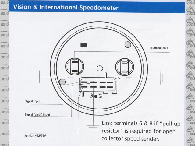
Image: a281336-VDO10021.JPG at LocostBuilders

Vdo rev counter | The Late Bay
A2C59519487 -- Tach With Display 85mm
VDO ViewLine Geschwindigkeitsmesser 200 Km/h Schwarz 85mm

Wiring Diagram For Aftermarket Tachometer

VDO "Extreme" 11000 RPM Recording Tachometer, Black Face, Black Housing
VDO Tachometer 0-515-012-037 | Manualzz

Manuals for VDO Equipment - MARINE DIESEL BASICS
VDO TACHOMETER : Installation manual
VDO-333-159 - 333159 - BLACK VISION TACHOMETER-8000 ...

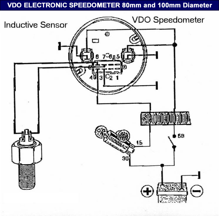
15+ Electric Speedometer Wiring Diagram | Types of electrical ...
Tachometer Installation and Operations Instructions
TheSamba.com :: Beetle - Late Model/Super - 1968-up - View ...
Wiring diagram for an O/B. | Page 2 | Boat Design Net
VDO speedo and TD5 sender q. | Defender Source Forum

Boats Parts & Maintenance Tacho Rev Counter & Trim Gauge with ...

WiFi Modul für Serien/Doppel-Lichtschalter, Sprachsteuerung über Alexa und google
0 Response to "39 vdo tachometer wiring diagram"
Post a Comment