40 5 wire door lock actuator wiring diagram
Tech-Tip-1041.pdf The fol- lowing diagrams show basic "5-wire" door lock wiring and can be used as references to guide you through the wiring of any "5-wire" system. standard "5- ...21 pages Power Door Locks & Wiring Diagram - YouTube Power Door Locks & Wiring Diagram. Смотреть позже.
door lock actuator wiring foolishness | Mercedes-Benz Forum The passenger door actuator hasn't worked since I bought the car and the driver's door just quit a month ago. You can see from the pictures why they weren't working. So I took the pictures before I pulled them apart but with all the crap around where the plug was and the bends in the wires...

5 wire door lock actuator wiring diagram
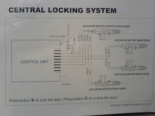
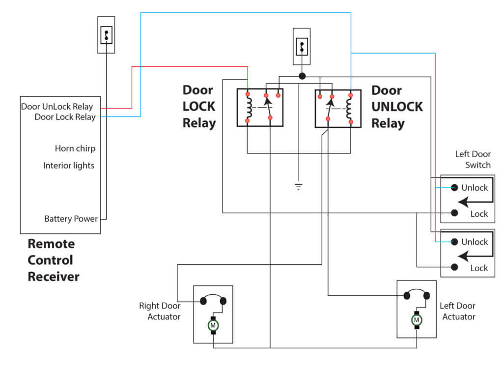
Central Door Locking System Wiring Diagram How Central Door Lock Actuators and Door Lock Relays Work In Detail. Here ... How power lock doors work from wiring diagram and keyless remote please subscribe to my channel Automotive Electronics ... PDF T-3986 GS EE 98 Adde | WIRING DIAGRAMS The wiring diagrams are grouped into individual sections. If a component is most likely found in a par-ticular group, it will be shown complete (all wires They are located in the junction block, and are used to protect such items as: power door lock motors, power windows, and various engine solenoids. PDF Electrical wiring diagram WIRING DIAGRAM. Provides circuit diagrams showing the circuit connections. (a) Locking device must be disengaged before the terminal locking clip can be released and the terminal removed from the connector. Engine Control Module(2GR-FE). Skid Control ECU with Actuator.
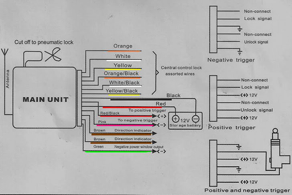
5 wire door lock actuator wiring diagram. 5-Wire Door Locks 3-wire door locks can be either positive (diagram below), or negative. There is either a constant ground or positive wire 5-wire door locks are a bit more complicated. Same applies to the lock wire, but this time the voltage is reversed, moving the door lock actuators in the opposite direction. 355 door locks, central locking | FerrariChat | Forum I think the door locking ECU is looking for a momentary earth to activate the lock actuator (as provided by the console switch). Ferrari wiring diagrams usually show switches in their normal driving positions, so I'm assuming the original diagram showed the switches in their latched (closed)... Exterior Door Handle Not Working - Door Lock Actuator - 5th Gen... Failed Door Lock Actuator Replacement Step-By-Step Install For the 5th Gen SR5 4Runner - Drivers exterior door You have the locking control cables and wire connectors still holding the panel to the door. There are cables that are connected to the handle/lock assembly on the backside of the panel. PDF GR00000300-90.fm | HOW TO READ CIRCUIT DIAGRAMS Indicates a wiring connector which is inside the equipment and which is not shown in the wiring harness configuration diagram. Front door lock actuator (rh). Etacs-ecu (door lock relay).
Front door lock actuator wiring | Alfa Romeo Forums The front passenger door lock actuator has given up the ghost. I would like to replace it with a universal door lock actuator instead of Alfa Romeo... I found the attached simpler schematic diagram from the internet. From my very little knowledge of electronics, I would connect the wires as... Universal 5 Wire Door Lock Actuator Wiring Diagram Collection Effectively read a wiring diagram, one provides to know how typically the components inside the system operate. For example , if a module is powered up All circuits are the same ~ voltage, ground, single component, and buttons. Universal 5 Wire Door Lock Actuator Wiring Diagram Source... Help with door lock actuator wiring. - Security Center - Car/Home... Ordered 2 wire actuators and got this: The package is labeled two wire but it's a 5 wire. No biggie, I didn't check right away and just put the box aside till this week. Shit happens. So the key less entry portion of the module is a simple 2 wire reverse polarity. my question is how do i get them to play... 5 Wire Door Lock Diagram Central Locking 5 Wire... | autocardesign ...Locking 5 Wire Door Lock Actuator Wiring Diagram just push the gallery or if you are interested in similar Gallery of 5 Wire Door Lock Diagram 5 Wire Door Lock Actuator Wiring Diagram can be a beneficial inspiration for those who seek an image according to specific categories like Wiring...
Wiring Diagram AUDI A3 2014 - Rear passenger side central locking... Wiring Diagram AUDI A3 2014 - Driver door control unit - Central locking SAFELOCK function warning lamp - Light for driver side interior door handle illumination - Light for driver side door loudspeaker Driver side central locking actuator. G415. Driver door exterior handle contact sensor. PDF Document WIRING DIAGRAM. 2. Provides circuit diagrams showing the circuit connections. HOW TO USE THIS MANUAL This manual provides information on Sensor A 3 A/C Dual Pressure SW A 4 A/C Magnetic Clutch and Lock Sensor A 5 A/T Fluid Temp. Sensor A 6 ABS Actuator A 7 ABS Actuator A 8 ABS... 93 SE door actuator wiring colors | Range Rovers Forum actuator colors door door lock actuator wiring wiring colors. That's a very basic diagram of what's going on inside the lock actuator, although I might have got the GB/UB mixed up.. I haven't got a 5 wire RRC actuator to test!! PDF Central locking system installation manual | INSTALLING WIRES Actuator installation example Figure 2. Actuator and door lock levers position. Figure 3. Connecting levers with joint Figure 4. Actuator stroke regulation. INSTALLING WIRES. 1. Make sure that all actuators are installed and connected before connecting red and black wire to power supply +12V...
5 Wires Central Door Locking Motor Master Central Locking ...
Door Lock Actuator Wiring Diagram Mes 5 Wire Great Central... Diesel Generator Control Panel Wiring Diagram BEK3-ZERO AMF CONTROLLER BEK3-CANBU AMF CONTROLLER The above illustrated diesel generator control panel wiring diagram is the typical connection wiring diagram of the BeK3 automatic mains failure controller.

Suzuki Swift GLS Remote Central Locking Wiring | Suzuki Forums
Power Door Lock Actuator Wiring Diagram Power Door Locks & Wiring Diagram Amazon Printed Books Amazon Kindle Edition ... How to do a Relay Power Door Lock Get the Book at Amazon: Get the Android Book-APP

3 Wire Positive Door Locks Relay Diagram | Door lock system ...
Diagnose and repair a power door lock actuator — Ricks Free Auto... Door lock actuators can also behave erratically. Some lock motor style actuators are designed with a rubber bumper stop component. Erratic operation can also be caused by a frayed wiring harness in the door hinge area or inside the actuator itself. Another symptom of a potential problem with the...

Car Locking System 5 Wire Single Gun Type Central Door Lock ...
how to manually trigger door lock actuator...see diagram Hi all Locked out of this parts car I juts got. From this diagram I have put 12v across all combinations of MZS MER & MVRFT. Do I have to apply 12v across any other wires in the diagram at the same time? Could the actuator be faulty? The PO must have had a bad gm5, he doesnt use the internet or...
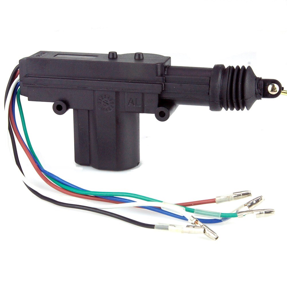
Door Lock Actuator 5 Wire
Automotive Power Accessories and Charging Systems Most of the door lock actuators are of the two-wire variety, no matter the manufacturer, OEM, or aftermarket supplier. Apply power to one wire and ground to the other and the actuator moves one way; reverse this and the actuator moves the other way. This is commonly referred to as "voltage...
Details zu Auto Zentral Verriegelung Antriebs Motor 12 V Auto Auto Schließ System Stel V6F7
This item: Universal Power Door Lock 2 Wire Actuator Kit VaygWay Universal Door Lock Actuator - Car Power Door Lock Actuator - 4 Pack Heavy Duty Actuators. I should add that no instructions are included. But it is fairly straight forward. If you initially hookup the wires in reverse you will lock this door while unlocking all the others and visa versa.
KnockLock Wiring Diagrams
How to Repair a Door Lock Actuator | YourMechanic Advice Sometimes a door lock actuator stops working completely. In some cars, a door lock actuator becomes noisy and produces a squeaking or buzzing noise when the power Then pry the motor up from its plastic portion and pull it out. The motor is not soldered in, so there are no wires to worry about.

electrical - Central Locking Help: Why are there 3 wires for ...
2-Wire Economy Door lock Actuator 2-wire version of SPAL-006. 2-Wire COMPACT Door lock Actuator. PDLA04 The compact motor runs parallel to the piston shaft for easier installation. 2-Wire Economy Door lock Actuator. 90-333S Import actuator with swivel shaft fits most vehicle doors. Mounting hardware included.
1x Central Türschloss System 2 Wire Sklave Tür Motor ...
Door Lock Actuator Wiring Diagram - Wiring Diagram Source 5 Wire Actuator Diagram Free Wiring Diagram For You. One wiring scheme is resistive rest at ground which has been used in the past by various. Autozone repair guide for your wiring diagrams doors 2006 door lockindicator schematics. 1999 Silverado Door Lock Actuator Wiring Diagram...

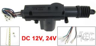
uxcell Car 5 Wire Power Door Lock Actuator for Central Locking System DC 12V
CHRYSLER 3/5 Wire Door Locking System - Bulldog Security Use this Diagram IF your Unit DOES NOT HAVE. On-Board Door Lock Relays. To 12 volts. 30 amp constant. Requires (2) fused at 30. #775 Relays.1 page
How to install central locking system from eBay inside car - Keyless entry system - Power door locks
Arduino - RFID/NFC Door Lock System | Arduino Tutorial The detailed instruction, code, wiring diagram, video tutorial, line-by-line code explanation are provided to help you quickly get started with Arduino. In this tutorial, we are going to learn how to make Arduino RFID/NFC Door Lock System using Arduino, RFID/NFC RC522 Kit, and electromagnetic lock.

Pin on Electrical Equipment & Supplies
Door lock actuator: problems, testing, replacement A failed door lock actuator will cause the door lock not to work when all other door locks are working. To diagnose, your mechanic may need to take the door cover off, check the door lock linkages and test the voltage at the door lock actuator, following the wire diagram.

12v 24v Auto Power Door Locks Central Locking System For Cars ...
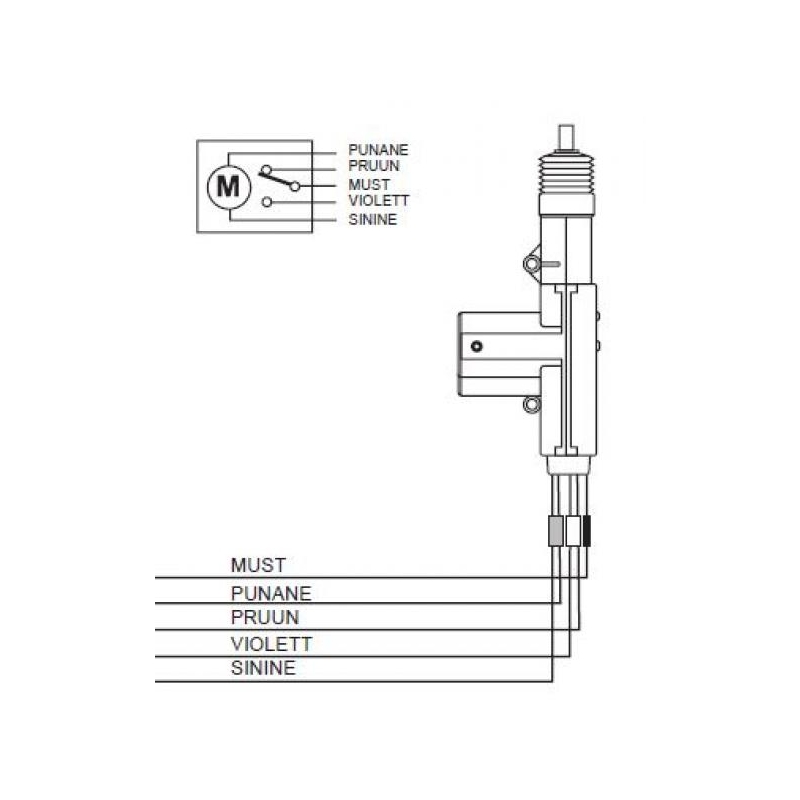
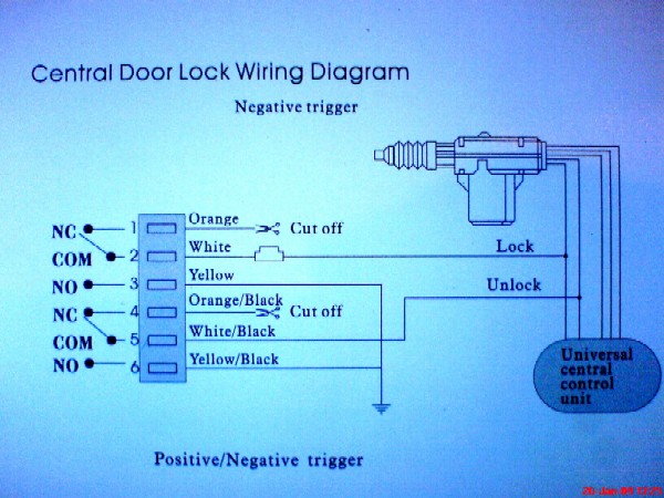
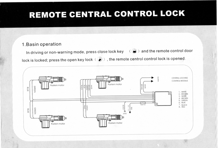
PDF Remote central lock | Wiring Procedure Operating a 5 wire actuator (front door) should now operate the lock/s connected to the 2 wire actuator/s (rear door). To connect to our keyless or alarm follow the wiring diagram below. For other alarms simply connect the alarms Lock and unlock wires to the white and brown wires on the...

5 Wire Door Lock Actuator Wiring Diagram Wire Center Best Of ...
Wiring door lock actuator | Hyundai Forums Im replacing the RR door lock actuator and everything was actually really easy except for the electrical connector. The wiring loop has a 5 pin female connector and the actuator has a Can i just connect the common to the negative to reduce it to 4? Does anyone know where I can find a wiring diagram?
BMW GM5 Wiring - Connections
PDF Electrical wiring diagram WIRING DIAGRAM. Provides circuit diagrams showing the circuit connections. (a) Locking device must be disengaged before the terminal locking clip can be released and the terminal removed from the connector. Engine Control Module(2GR-FE). Skid Control ECU with Actuator.
Door Locks : Custom Car Stereo - Complete Car Audio Building ...
PDF T-3986 GS EE 98 Adde | WIRING DIAGRAMS The wiring diagrams are grouped into individual sections. If a component is most likely found in a par-ticular group, it will be shown complete (all wires They are located in the junction block, and are used to protect such items as: power door lock motors, power windows, and various engine solenoids.
Central door locking actuator 5 wire @ proteam
Central Door Locking System Wiring Diagram How Central Door Lock Actuators and Door Lock Relays Work In Detail. Here ... How power lock doors work from wiring diagram and keyless remote please subscribe to my channel Automotive Electronics ...

M616-8182 Car Remote Control Central Lock Alarm Device With Motor System HNB

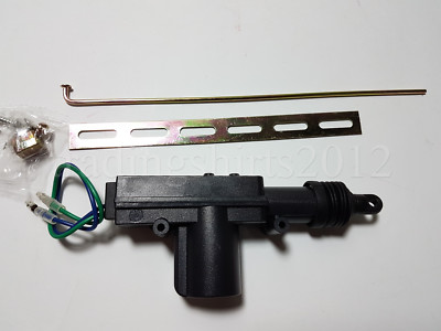
Vision 5-wire central locking motor with bracket.
remote central locking

Door lock wiring | VW Vortex - Volkswagen Forum
Door Locks : Custom Car Stereo - Complete Car Audio Building ...
Multiple Wire Power Door Lock Systems, Add Auto Lock/Unlock
DIY Tips: How to install car alarm with central locking

remote central locking
Central locking wiring for Honda Civic from LF-Q025A alarm ...
Power Locks: I Have Purchased a Power Door Lock Kit and Would ...

GT 121 - Installation guide

Universal car alarm system and remote control central door ...
Power Door Lock Wiring Diagram?: Both Sides Quit at the Same ...
New Kae Central Door Lock Relay 3802110 Volvo OE 3523739 on ...

INSTALLATION DIAGRAMS Remote Starter Install Video Click ...
Power door locks don't work — Ricks Free Auto Repair Advice ...

Car Alarm / Keyless Entry / Central Lock Diagram
SUNSKY - Car Auto Main Driving Seat Door Central Lock Keyless ...

Automotive Power Accessories and Charging Systems

Door Lock Upgrade System Instructions Combo - Digital Door ...

Anyone know how the power door lock actuators work? - Pelican ...

Power Door Lock Actuator Wiring Diagram | Door locks ...

Sydien 2 Pack 5 Wire Car Power Door Lock Actuator for Central ...
0 Response to "40 5 wire door lock actuator wiring diagram"
Post a Comment