39 cantilever beam free body diagram
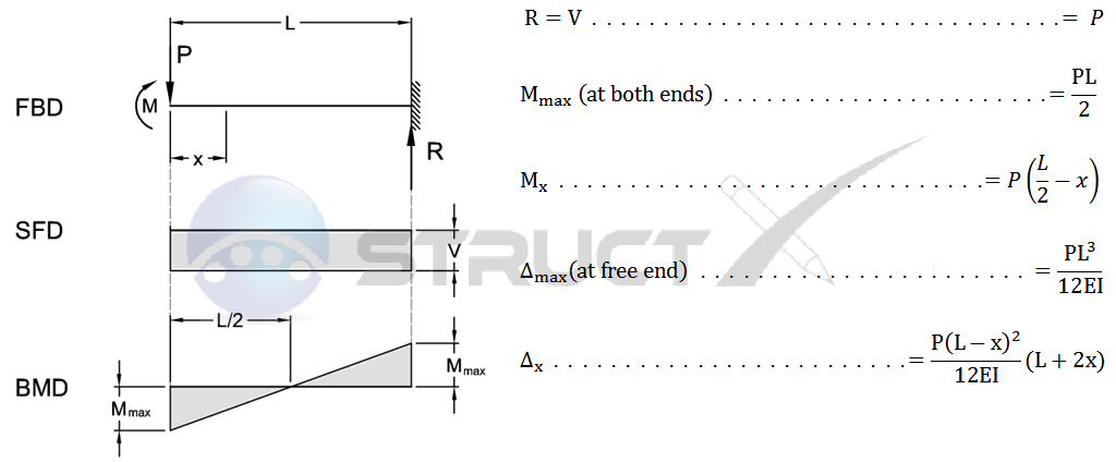
Cantilever Beam, End Load | MechaniCalc The standard beam equations for a cantilever beam loaded at the free end are given below: Max Deflection The Free Body Diagram (FBD) is shown below. From the FBD it can be seen that the forces balance and the beam is in static equilibrium. Free body diagrams | CIVIL engineering Free body diagrams may not seem necessary in the relatively simple current applications, but as problems become more complex, their usefulness increases. The following is the process for determining the reaction at the wall for a cantilever beam. A FBD is first drawn of the beam.
Fig. 4.4. Cantilever beam. The free-body diagram of the beam is shown in Figure 4.6b. First, compute the reactions at the support B. Applying the conditions of equilibrium suggests the following: Shearing force and bending moment functions.

Cantilever beam free body diagram
Free body diagram - Wikipedia A free body diagram consists of a diagrammatic representation of a single body or a subsystem of bodies isolated from its surroundings showing all the forces acting on it. In physics and engineering, a free body diagram (FBD; also called a force diagram)... Cantilever Free Body Diagram Example | Statics - YouTube Введите запрос. Войти. Cantilever Free Body Diagram Example | Statics. Смотреть позже. Поделиться. The video, then, displays a cantilever beam subjected to a point load of 20 N at free edge of the beam in downward direction. Cantilever beam free body diagram Free body diagram. Cantilever beam boundary conditions. The reaction Forces and moment at A can be calculated by applying Equilibrium conditions Ans: For a cantilever beam subjected to uniformly distributed load over the beam's length, the Shear force diagram's shape will be a linear curve and...
Cantilever beam free body diagram. PDF Untitled Document The free body diagram of the beam is shown below along with their M/EI diagrams. The unknowns can be obtained with the condition that the vertical deflection and slope at B are zero. PDF Shear Forces and | Solution 4.3-4 Cantilever beam Free-body diagram of section CB. Point C is at the midpoint of the beam. Problem 4.5-22 The cantilever beam shown in the figure supports a concentrated load and a segment of uniform load. Draw the shear-force and bending-moment diagrams for this cantilever beam. PDF For example, a simply-supported beam Cantilever beams and simple beams have two reactions (two forces or one force and a couple) and these reactions can be obtained from a free-body A free body diagram of the portion of the beam between the left end and plane a-a is shown in Fig. 3.3. A study of this section diagram reveals that a... Cantilever Beam Free Body Diagram - Free Catalogs A to Z Lecture 23: Cantilever Free Body Diagram Example. 7 hours ago Cantilever Free Body Diagram Example by SpoonFeedMe. The video, then, displays a cantilever beam subjected to a point load of 20 N at free edge of the beam in downward direction.
PDF Microsoft Word - report5.doc (17-b) Free body diagram of panels. Since this is an unsymmetrical cross-section beam, it is expected that its cross-section will warp under the effect of bending shear Consider the beam acts as a cantilever beam. 28. with the bending moment existing at section (A) being greater than that... Everything You Should Know About Cantilever Beams A cantilever beam is a rigid structural element supported at one end and free at the other, as shown in Figure-1. The bending and shear force diagram is determined for all possible load combinations to design a cantilever beam for a structure. Cantilever Beam Free Body Diagram - Wiring Site Resource A beam supported by a column and a knee frane hinged cantilever beam with cable support. As with all calculations care must be taken to kee... Cantilever Beam Calculator | calcresource - Cantilever beam with partially distributed uniform load. The tool calculates and plots diagrams for these quantities Removing the singe support or inserting an internal hinge, would render the cantilever beam into a mechanism: a body the moves without restriction in one or more directions.
PDF Extrusion-based Additive Manufacturing of Silicone Elastomer Parts Figure 4.2: Free body diagrams of the extrusion-based AM forces between the silicone fluid and deposit layer (or build plate) with increasing This section describes the procedure of converting the measured displacement of the cantilever beam to Ft and Fn. Three free body diagrams, as shown... Free Vibration of a Cantilever Beam (Continuous System) For a cantilever beam subjected to free vibration, and the system is considered as continuous system in which the beam mass is 4.1(a) shows of a cantilever beam with rectangular cross section, which can be subjected to bending vibration by giving a small initial displacement at the free end; and Fig. Bending moment and shear force diagram of a cantilever beam In this article Learn :cantilever beam Bending moment diagram B.M.D. and shear force diagram S.F.D. of a cantilever beam having point load at the end,several point loads,U.D.L. Over Whole Span ,U.D.L. not over the whole span,U.D.L. from support to some distance,U.D.L... PDF M4.3-Unified08.ppt | FREE BODY DIAGRAM 1. Draw Free Body Diagram 2. Apply Equilibrium Example: Cantilevered Flag Figure M4.3-8 Geometry and free body diagram of cantilevered flag. Figure M4.3-14 Free body diagram of beam with "cut" at point x = L/2.
classical mechanics - Bending moment in a cantilever beam ...
(PDF) Modeling and Quasi-Static Analysis of a Shape Memory Polymer... Figure 3: Free-body diagram for an increment of a cantilever beam. Three cases of heated recovery are selected: unconstrained free strain recovery, stress recovery under full constraint at the pre-deformation strain level (no low temperature unloading), and stress recovery under full constraint...
Beam Reactions and Diagrams – Strength of Materials ...
Free Beam Calculator | Optimal Beam Easy to use online statically indeterminate beam calculator. Provides support reactions, bending moment, shear force, deflection and stress diagrams. Free Beam Calculator for Statically Indeterminate Beams.

Draw Bending Moment & Shear Force Diagrams - Cantilever Beam
Beam Calculator Online (Calculate the reactions, Draws Bending...) Bending moment diagram (BMD) Shear force diagram (SFD) Axial force diagram. Invert Diagram of Moment (BMD) - Moment is positive, when tension at the bottom of the beam. Calculate.
Shear force and Bending Moment diagram for cantilever
PDF Mechanical Vibrations: Theory and Applications, SI Edition, 1st ed. 2.9 Free-Body Diagram Method. 2.10 Static Deflections and Gravity. 2.11 Small Angle or Displacement Assumption. Particles in an elastic body may move relative to one another as motion occurs. Particles A and C lie along the neutral axis of the cantilever beam of Figure 1.8, while particle B.

SHEAR FORCE AND BENDING MOMENT DIAGRAM FOR CANTILEVER BEAM ...
Lecture 22: Simply Supported Beams Free Body Diagram Example Advanced Free Body Diagram Beam Example. Introduction to Axial & Shear Forces and Bending Moments. Mechanics, the study of forces and physical bodies, underpins a very large proportion of all forms of engineering. A thorough understanding of mechanics is essential to any successful...
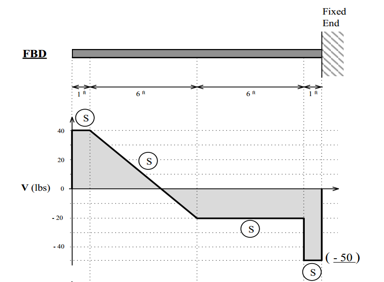
Solved The Shear diagram for a cantilever beam, fixed at the ...
Cantilever Beams and Continuous Beams - Mo Civil Engineering determinate or indeterminate by drawing free body diagram for a structure or part of it and comparing a number of unknown forces and moment Let consider a slab supported by beams and columns, to begin structural analysis for each member, we need to know the amount of load transferred to this...
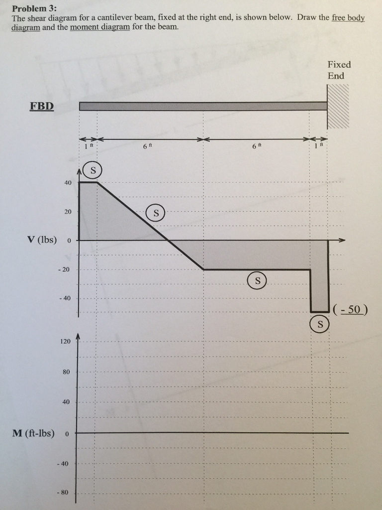
Solved The shear diagram for a cantilever beam, fixed at the ...
Cantilever Beams - an overview | ScienceDirect Topics Bimorph piezoelectric cantilever beam is assembled with beam material and two piezoelectric ceramic strips, conductive adhesive, and two piezoelectric films by series or parallel connection A cantilever beam is fixed at one end and free at the other end; it has fixed-free boundary conditions described as.
Example 2
PDF Comparing Strain Gage Rigid-body motion is the rotation or translation of a body as whole (Dally). This definition ignores elastic and plastic deformations, indicating that Students conducting this lab will be first asked to calculate microStrains to be expected when loading a cantilever beam with a single load on its free end.

Static Stress with Linear Material Models | Search | Autodesk ...
V & M Diagrams | PDF | Bending | Beam (Structure) Free-body diagram of left-hand half of beam: Point E is at the midpoint of the beam. q A b L/2 RB E V M = 0 (Given). Problem 4.5-4 The cantilever beam AB shown in the figure is subjected to a concentrated load P at the midpoint and a counterclockwise couple of moment M1 PL/4 at the free end.

a) A cantilever under a concentrated load and (b) the free ...
PDF Reinforced-Concrete-Cantilever-Beam-Analysis-and-Design... Reinforced Concrete Cantilever Beam Analysis and Design (ACI 318-14) Cantilever beams consist of one span with fixed support at one end and the other end is free. There are numerous typical and practical applications of cantilever beams in buildings, bridges, industrial and special structures.
![Cantilever Beam: Shear Force and Bending Moment Diagram [SFD BMD Problem 2] By Shubham Kola | Facebook](https://lookaside.fbsbx.com/lookaside/crawler/media/?media_id=257535155732524&get_thumbnail=1)
Cantilever Beam: Shear Force and Bending Moment Diagram [SFD BMD Problem 2] By Shubham Kola | Facebook
What is the image of the cantilever beam free end is supported to stutt? Cantilever Beam: Beam has one end fixed and other end free. Single Overhanging Beam: Beam freely supported at two points and having one ends extending beyond the supports. Here are some diagrams I created that hopefully help illustrate the point.

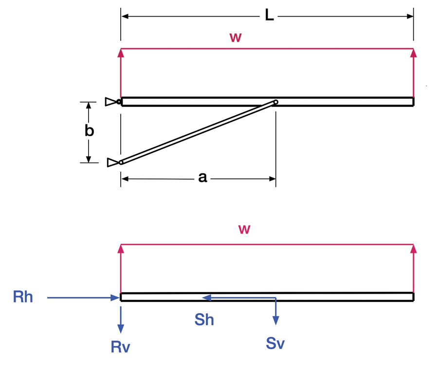
The cantilever beam model with both a parallel and diagonal ...
Free Online Beam Calculator for Cantilever or Simply Supported Beams Free online beam calculator that calculates the reactions, deflection and draws bending moment Any changes made will automatically re-draw the free body diagram any simply supported or cantilever beam. This includes calculating the reactions for a cantilever beam, which has a bending moment...

Shear Force and Bending Moment diagram for cantilever beam ...
Cantilever beam free body diagram Free body diagram. Cantilever beam boundary conditions. The reaction Forces and moment at A can be calculated by applying Equilibrium conditions Ans: For a cantilever beam subjected to uniformly distributed load over the beam's length, the Shear force diagram's shape will be a linear curve and...
6.2 Shear/Moment Diagrams – Engineering Mechanics: Statics
Cantilever Free Body Diagram Example | Statics - YouTube Введите запрос. Войти. Cantilever Free Body Diagram Example | Statics. Смотреть позже. Поделиться. The video, then, displays a cantilever beam subjected to a point load of 20 N at free edge of the beam in downward direction.

Beam Reactions and Diagrams – Strength of Materials ...
Free body diagram - Wikipedia A free body diagram consists of a diagrammatic representation of a single body or a subsystem of bodies isolated from its surroundings showing all the forces acting on it. In physics and engineering, a free body diagram (FBD; also called a force diagram)...
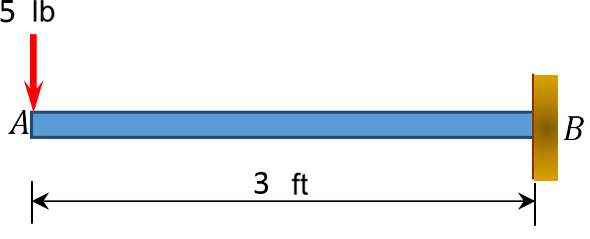
Cantilever Beam - Point Load and Bending Moment at Free End
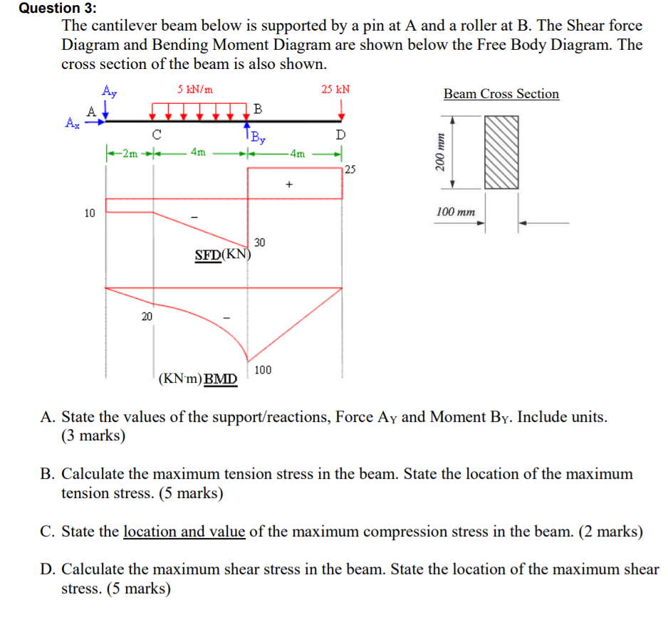
Solved Question 3: The cantilever beam below is supported by ...
![[Ex. 07] Shear Moment Diagram Cantilever Beam Distributed Load Part I](https://i.ytimg.com/vi/qMk5IVKcZQM/maxresdefault.jpg)
[Ex. 07] Shear Moment Diagram Cantilever Beam Distributed Load Part I
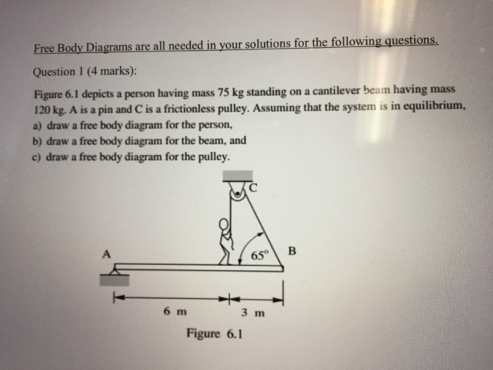
Solved Free Body Diagrams are all needed in your solutions ...
Cantilever beam example where students need to complete the ...
Mechanics of Materials Chapter 4 Shear and Moment In Beams

Free body diagram of the three segments of the cantilever ...
Stressing Structure

Shear Force and Bending Moment Diagram for Cantilever Beam ...
Chapter 4: Internal Forces in Beams and Frames” in ...

Everything Modelling and Simulation: A Fixed Free Cantilever ...

Bending moment and shear force diagram of a cantilever beam
1.4: Internal Forces in Beams and Frames - Engineering LibreTexts
Beam Reactions and Diagrams – Strength of Materials ...

Cantilever beam Shear Force and Bending Moment diagram with Triangular load
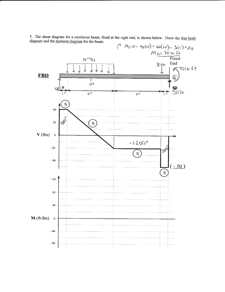
Solved 5. The shear diagram for a cantilever beam, fixed at ...

A cantilever beam AB is subjected to uniformly distributed ...

Calculating Shear Force and Bending Moment at the Support for Cantilever Beams
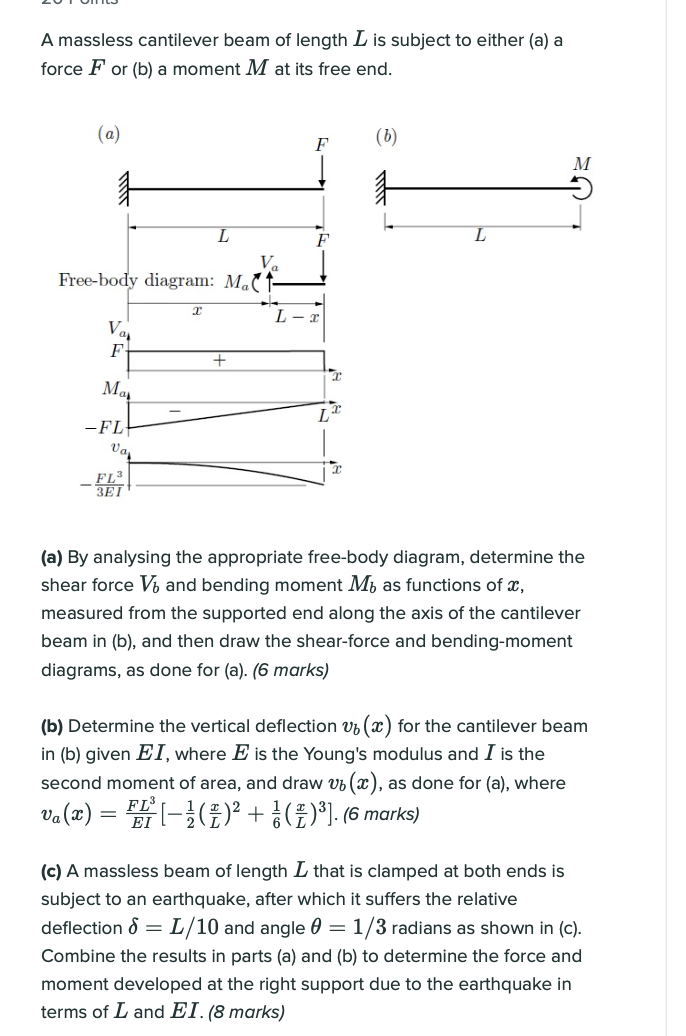
Solved A massless cantilever beam of length L is subject to ...

Cantilever beam response: support reactions, beam moment ...
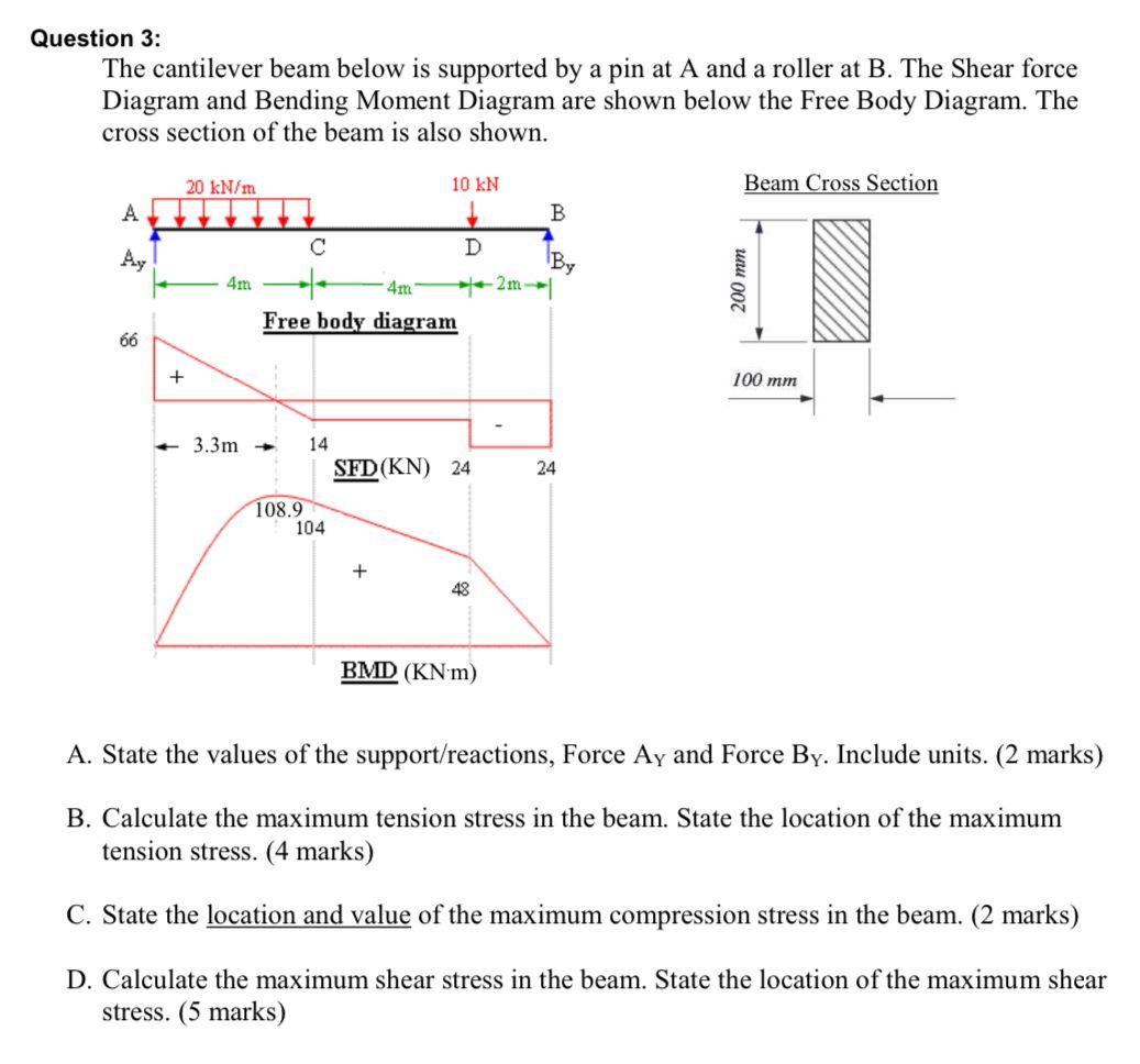
Solved Question 3: The cantilever beam below is supported by ...
Shear Force and Bending Moment Diagram for Cantilever Beam ...
What are Free Body Diagrams?
How to Draw a Free Body Diagram - Simply Supported Beam with ...
0 Response to "39 cantilever beam free body diagram"
Post a Comment