38 two force member free body diagram
PDF Engineering Mechanics: Statics - Campus Tour Free-Body Diagram First step in the static equilibrium analysis of a rigid body is identification of all forces acting on the body with a free-body diagram. • Select the extent of the free-body and detach it from the ground and all other bodies. • Indicate point of application, magnitude, and direction of external forces, including the ... 6.2. Static Force Analysis of Machinery The free-body diagrams of the links in the four-bar mechanism are redrawn below. In this case to simplify the calculations we note that Fij = -Fji for the joint forces. Furthermore, since link 3 is a two-force member, F23 and F43 are equal, opposite and their line of action is along AB.
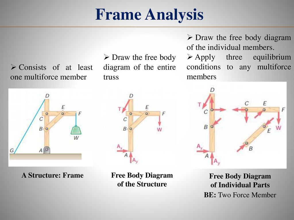
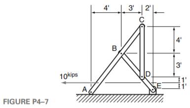
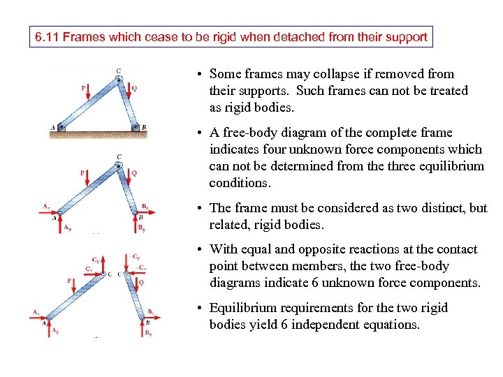
PDF FRAMES AND MACHINES - Purdue University a) Identify any two-force members in the frame. b) Draw the overall free body diagram and the individual free body diagrams of members ACE and BCD, and pulley E. c) Determine the forces at pin C on member BCD.
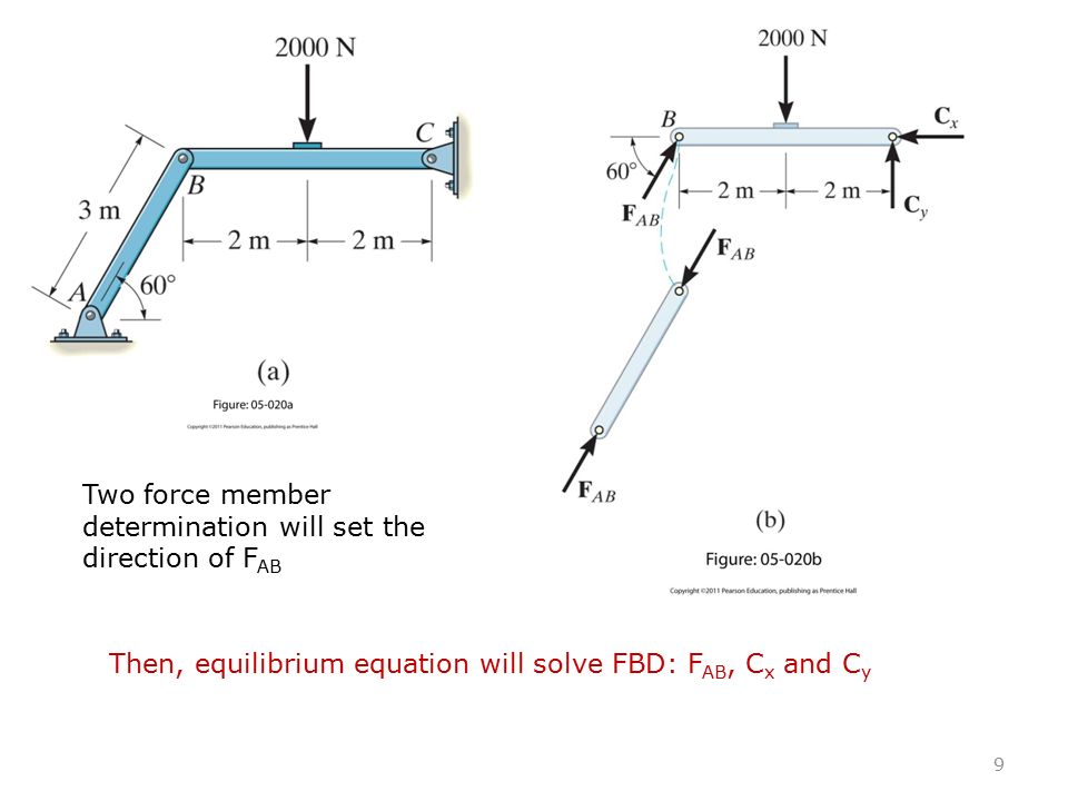
Two force member free body diagram
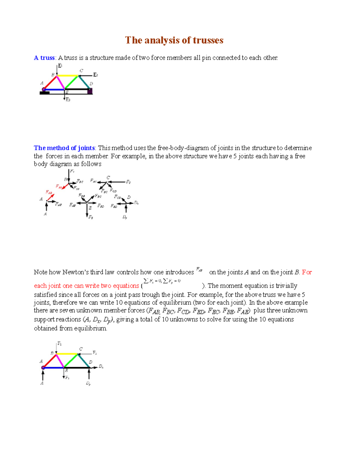
The analysis of trusses - University of Nebraska-Lincoln made of two force members all pin connected to each other. The method of joints: This method uses the free-body-diagram of joints in the structure to determine the forces in each member. For example, in the above structure we have 5 joints each having a free body diagram as follows Note how Newton's Determine the horizontal and vertical components force at ... Free Body Diagram:The solution for this problem will be simplified if one realizes that member [latex]BC[/latex] is a two force member. Equations of. Results. See All Results. Question: Structural Analysis [EXP-546] Determine the horizontal and vertical components force at pins A and C of the two-member frame. PDF ENGR-1100 Introduction to Engineering Analysis FREE-BODY DIAGRAMS (Section 5.2) 2. Show all the external forces and couple moments. These typically include: a) applied loads, b) support reactions, and, c) the weight of the body. Idealized model Free-body diagram (FBD) 1. Draw an outlined shape. Imagine the body to be isolated or cut "free" from its constraints and draw its outlined shape.
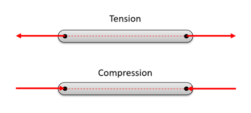
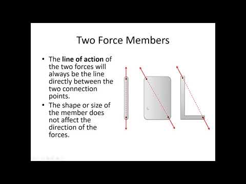
Two force member free body diagram. A system of two bodies and wall | Physics Forums If you can answer those two questions you can find the resistive force extremely easily. I think you must take a step back. Drawing free body diagrams helps you to correctly think about what forces act. Until you can (correctly) draw the free body diagrams for A and B, I don't think you will be able to answer the question (IMHO). Edited Two force members explained (statics) - YouTube This engineering statics tutorial explains what two force members are and how they can be used to solve frames, machines, and truss problems. Basically, if a... PDF Equations of Equilibrium & Two-and Three-force Memebers TWO-FORCE MEMBERS A two-force member is a rigid body with no force couples, acted upon by a system of forces composed of, or reducible to, two forces at different locations. The most common example of the a two force member is a structural brace where each end is pinned to other members as shown at the left. In the diagram, notice that member ... Recap of Two Force Members - YouTube This video recaps the concept of two force members including how to identify them visually, and how this information can then be used for a free body diagram.
Solved Question 24 5 pts Which one of the ... - Chegg.com When a free-body diagram of a connected group of members of a frame is drawn, the forces between the connected parts of the group are not shown on the free-body diagram of the group Forces common to two members which are in contact act with equal magnitude, but opposite sense on the respective opposing free-body diagrams of the separate members. Free Body Diagrams: Determining Internal ... - Top Dog Engineer The steps include: STEP 1: Identifying two force members. STEP 2: Drawing free body diagrams of each component. STEP 3: Solving for the external forces by applying equations of equilibrium. STEP 4: Cutting the body at the location of interest. STEP 5: Solving for the internal forces at the cut location using the equations of equilibrium. PDF ENGR-1100 Introduction to Engineering Analysis b) Recognize two-force members. • Two-Force Members •Concept Quiz •Group Problem Solving •Attention Quiz APPLICATIONS The truck ramps have a weight of 400 lb each. Each ramp is pinned to the body of the truck and held in the position by a cable. How can we determine the cable tension How are the idealized model and the free body diagram ... Structural Engineering: Free Body Diagrams - Top Dog Engineer The steps include: STEP 1: Identifying two force members. STEP 2: Drawing free body diagrams of each component. STEP 3: Solving for the external forces by applying equations of equilibrium. STEP 4: Flipping the direction of negative force vectors. If you want to learn from the ground up, please watch the video!!
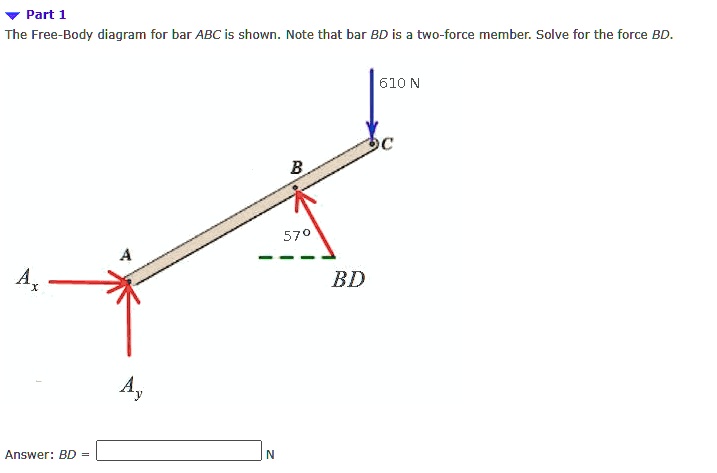
ESCI 202 Module 01 Chapter 1-2 Self ... - Course Hero Question 12 In drawing the free body diagram of the structure shown , the force acting at C is directed toward B .This is because BC is a _ two _ _ force _ member Question 13 For a two - dimensional static problem of rigid body using Cartesian coordinates , Newton 's first law results in _ three _ scalar equations ? PDF Free Body Diagrams - The University of Memphis 9 Free Body Diagrams Wednesday, October 3, 2012 Equilibrium Expanded ! When we remove that restriction, we can add a second condition for equilibrium M ∑=0 F ∑=0 10 Free Body Diagrams Wednesday, October 3, 2012 Equilibrium Expanded ! The sum of the forces acting on a system must be equal to 0 ! The sum of the moments generated by the For the frame and loading shown, draw the free-body ... We note that BD is a two-force member.Free body: ABC. Results. See All Results. Question: Vector Mechanics for Engineers: Statics - Solutions Manual [EXP-4663] For the frame and loading shown, draw the free-body diagram(s) needed to determine the forces acting on member ABC at B and C. Step-by-Step. Report Solution. Verified Solution. Free Body Diagram Questions and Answers - Study.com In each case, identify any two-force members, and then draw the free -body diagrams of each member of the frame. View Answer A collar B of weight W can move freely along the vertical rod.
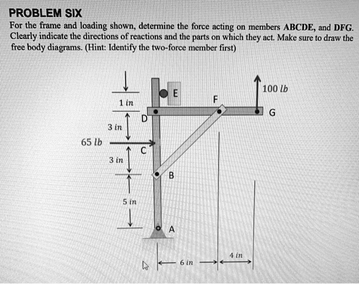
SOLVED:PROBLEM SIX For the frame and 'loading shown_ ...
Free Body Diagram: Definition, Purpose, Examples, Steps ... All forces and moments acting on the object are represented using two dimensional or three-dimensional representation using the free body diagram or FBD concept. As the forces are vector quantity, FBD is also known as a vector diagram. In this article, we will explore more details about the free body diagram. Purpose of the Free Body Diagram

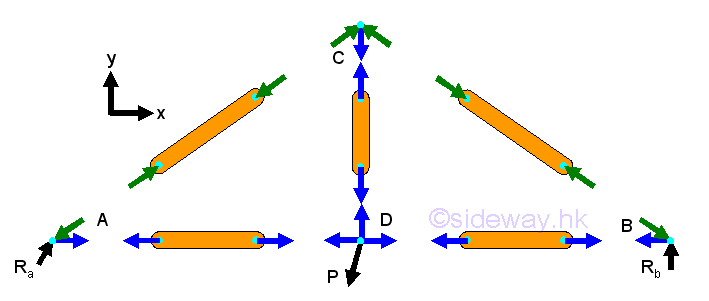
Two-force member FBD | Download Scientific Diagram
PDF Example 1 - Etu note that BC is a two-force membersince only two forces act on it. For this reason, the reaction at C must be horizontal as shown. Since BA and BD are also two-force members, the free-body diagram of joint B is shown in Fig. 1-7c.Again, verify the magnitudes of the computed forces and Free-Body Diagram.Using the result for the left section AG
FRAMES AND MACHINES Learning Objectives 1). To evaluate the ...
PDF 5 Solutions 44918 - TURMA 2014.2 - ENGENHARIA CIVIL Draw the free-body diagram of the 50-kg paper roll which has a center of mass at G and rests on the smooth blade of the paper hauler. Explain the significance of each force acting on the diagram. (See Fig. 5-7b.) B 30 35 mm A G 5-2. Draw the free-body diagram of member AB, which is supported by a roller at A and a pin at B. Explain the
Three-Force Member Example Problem
Free body diagram drawing for a two force members on machine ... Jul 12, 2015 · I drew a free body diagram of Members EA with the initial force applied. Since A and B are two force members, ##F_ {AB}## is drawn opposite direction in free body diagram BCD. However when I solve the the equations I get that P is opposite to the Free body diagram drawn. Why is that is there some mistake? [/B] Moments about ##E## yields ##M_E=2 ...
Lab: Simple form truss 1 day Purpose: Demonstrate and ...
PDF Chapter 1. Review of Static Equilibrium - Purdue University Which members, if any, are two force members? How does the existence of two-force members affect the FBDs of non-two-force members in the frame. Shown to the right of the structure are the FBDs of the individual members of the frame. Note that member CE is a two-force member since forces are applied at only two locations (C and E).
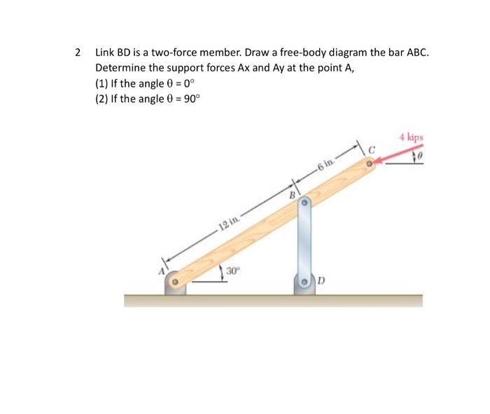
Solved 2 Link BD is a two-force member. Draw a free-body ...
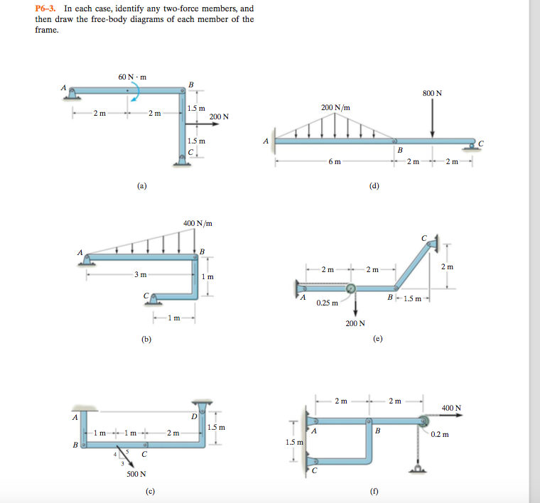
PDF College of Engineering and Computer Science | Wright State ... In each case, identify any two-force members, and draw the free-body diagrams of each member of the E-žme. 60 N m 1.5 m 200 N 1.5 m 400 N /m

In each case, identify any two force members, and then draw ...
PDF T The Free Body AB Diagram The Concurrent System of applied and reactive forces acting on a body, are called free body diagrams. The whole system of applied and reactive forces acting on a body must be in a state of equilibrium. Free-body diagrams are, consequently ,often called equilibrium diagrams. Drawing equilibrium diagrams and finding reactions for loaded structural members is a
Statics – no motion
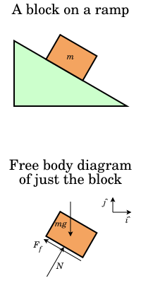
Free Body Diagrams, Tutorials with Examples and Explanations Example 8 : A system with two blocks, an inclined plane and a pulley. A) free body diagram for block m 1 (left of figure below) 1) The weight W1 exerted by the earth on the box. 2) The normal force N. 3) The force of friction Fk. 4) The tension force T exerted by the string on the block m1. B) free body diagram of block m 2 (right of figure below)
Mechanics Map - Two Force Members
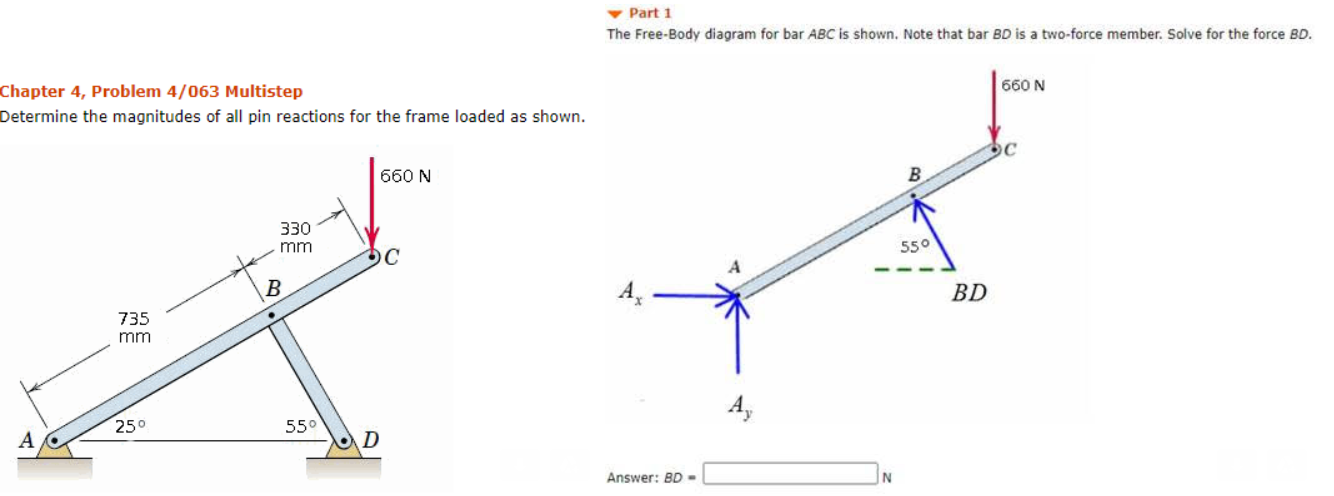
Solved Part 1 The Free-Body diagram for bar ABC is shown ... Civil Engineering questions and answers. Part 1 The Free-Body diagram for bar ABC is shown. Note that bar BD is a two-force member. Solve for the force BD. 660 N Chapter 4, Problem 4/063 Multistep Determine the magnitudes of all pin reactions for the frame loaded as shown. 660 N B 330 mm 550 B BD 735 mm 250 550 A D Answer: BD-.
SOLVED:Part 1 The Free-Body diagram for bar ABC is shown ...
2-force members.pdf - A two-force member is a body that ... A two-force member is a body that has forces (and only forces, no moments) acting on it in only two locations. In order to have a two-force member in static equilibrium, the net force at each location must be equal, opposite, and collinear. This will result in all two-force members
Section 5.3-5.4
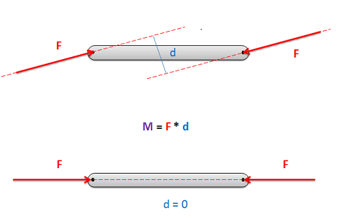
PDF Equations of Equilibrium & Two- and Three-force Members TWO-FORCE MEMBERS & THREE FORCE-MEMBERS (Section 5.4) The solution to some equilibrium problems can be simplified if we recognize members that are subjected to forces at only two points (e.g., at points A and B). If we apply the equations of equilibrium to such a member, we can quickly determine that the resultant forces at A and B must
Analysis of Trusses - lecture notes - ME 273 - Statics - BU ...
Two- and Three-Force Members - Massachusetts Institute of ... The free body diagram of the system can be seen in the diagram below. The magnitude and the line of action of the force at F, 10 Kips, is known. and opposite to the force C of the two-force member CB. The line of action of the forces at point F and point C intersect at X. The line of action (Why is this?)

Statics Study Pack -- for Engineering Mechanics: Statics ...
What is a Free-Body Diagram and How to Draw it (with ... A free-body diagram is a representation of an object with all the forces that act on it. The external environment (other objects, the floor on which the object sits, etc.), as well as the forces that the object exerts on other objects, are omitted in a free-body diagram. Below you can see an example of a free-body diagram:

Example 4
PDF ENGR-1100 Introduction to Engineering Analysis FREE-BODY DIAGRAMS (Section 5.2) 2. Show all the external forces and couple moments. These typically include: a) applied loads, b) support reactions, and, c) the weight of the body. Idealized model Free-body diagram (FBD) 1. Draw an outlined shape. Imagine the body to be isolated or cut "free" from its constraints and draw its outlined shape.

In each case, identify any two-force members, and then draw ...
Determine the horizontal and vertical components force at ... Free Body Diagram:The solution for this problem will be simplified if one realizes that member [latex]BC[/latex] is a two force member. Equations of. Results. See All Results. Question: Structural Analysis [EXP-546] Determine the horizontal and vertical components force at pins A and C of the two-member frame.
Solved Identify any two force members and then draw the free ...
The analysis of trusses - University of Nebraska-Lincoln made of two force members all pin connected to each other. The method of joints: This method uses the free-body-diagram of joints in the structure to determine the forces in each member. For example, in the above structure we have 5 joints each having a free body diagram as follows Note how Newton's
ME 141 Engineering Mechanics Portion 4 Analysis of Structure ...

Chapter 6, Question 3PP | Solutions for Hibbeler's ...

Equations of Equilibrium In Structural analysis - Mo Civil ...
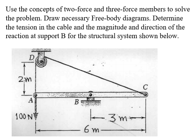
Solved Use the concepts of two-force and three-force members ...
Statics - Roy Mech
Solved Part 1 The Free-Body diagram for bar ABC is shown ...

Statics eBook: Two- and Three-Force Members

Statics eBook: Two- and Three-Force Members
Statics - TAM 210 & TAM 211
Free body diagram - Wikipedia
STATIC FORCE ANALYSIS
Solved) - The two-force member CD has a compressive load of 2 ...

Statics eBook: Two- and Three-Force Members
Mechanics Map - Two Force Members

4 m 3 m 3 m 6 m 3 m Rough/3 Neglecting the weight of the ...

In each case, identify any two-force members, and then draw ...
Calculating a force on a member (Statics) | Physics Forums
Two- and Three-Force Members
6 7 Analysis of trusses By the method
5.2: Two-Force Members - Engineering LibreTexts
Solved] The free-body diagram for rigid member ABC is shown ...
Static Analysis Static Analysis, Internal Forces, Stresses ...
0 Response to "38 two force member free body diagram"
Post a Comment