37 marine inverter wiring diagram
RV Electrical Diagram (Wiring Schematic) - Camper Guide Mar 15, 2020 · View our RV wiring Diagram to understand how an RV electrical system works and the diference between AC and DC power. ... 12 Volts of DC power will be pulled from the house batteries. That power will run through the RV’s inverter, and the produced 120 Volts of AC power will run whatever you connected to the power outlets: microwave, phone ... Grounding and Circuit Protection for Inverters and Battery ... 2. Install the AC wiring to the charger or inverter including an AC grounding conductor of a size equal to the current carrying conductors unless the circuit exceeds 30A, in which case the grounding conductor may be one size smaller (E11.16.1.3.8.2). This is the typical grounding conductor that you would see with any AC appliance and returns ...
PDF Installing Inverter-Charger Systems Revision - JTB Marine JTB Marine Corporation, 727.323.2500, Revision 1/08 11 SystemDesign: LoadCalculations • First some definitions: - Energy is a measure of the ability of a system to do work; the units are watt-hrs - Power is rate of energy delivery; the units are watts • One thousand watts are equal to one kilowatt

Marine inverter wiring diagram
Inverter Installations; What You Need to Know | Steve D ... If you are considering having an inverter installed, have the work carried out by an ABYC certified marine electrician, or at least by an electrician or yard that is a member of ABYC. Tell the technician you want to be sure it complies with sections E-11 'AC and DC Electrical Systems', and section A-3 'Battery Chargers and Inverters'. PDF OWNER'S MANUAL - Xantrex Part No. 90-0113-00 Fdmman2.p65 2/98 OWNER'S MANUAL FREEDOM COMBI TM INVERTER/CHARGERS FREEDOM MODELS 10, 15, 20, 25 ® A Valley Forge Company UL How to Wire an Inverter in an RV [Schematics in PDF ... In the above diagram, three batteries are connected in parallel to each other and power up the inverter's DC terminals. A fuse box is installed on the positive (red) wire. If we connect high capacity and a greater number of batteries to the battery bank, then the time for which we can take power from the batteries is increased.
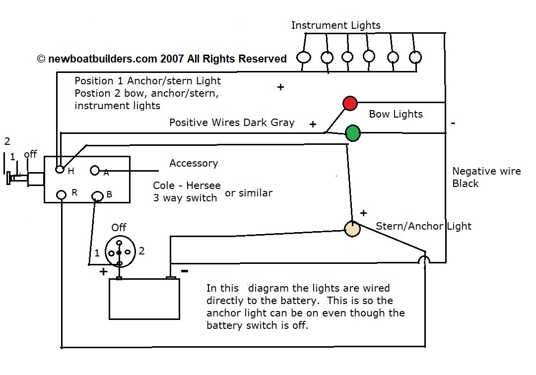
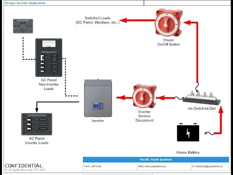
Marine inverter wiring diagram. Wiring Diagrams - AC DC Marine Inc D. Technical Information. An inverter converts DC power to AC power and changes the voltage; it is a power adapter. It allows a battery-based system to run conventional AC appliances directly or through conventional home wiring. There are ways to use DC directly, but for a modern lifestyle, you will need an inverter for the vast majority, if ... How to wire inverter/generator/shore power | The RV Forum ... Guest. Gary RVer Emeritus said: With that diagram, all power flows through the inverter at all times, so the inverter has to be able to handle at least 30A (3600 watts) if the RV has a 30A load center [Much more if a 50A RV]. If not, the internal breaker in the inverter will trip before you reach full load capability. Wiring Inverter Load Group (sub Panels) - Blue Sea Systems The inverter appropriate loads, such as the TV or microwave, are supplied from the Inverter Load Group. The last breaker on the main AC bus is labeled Inverter Input. This is the feed for the automatic transfer switch, which is located inside most modern inverters approved for marine use. Marine Inverter Wiring Diagram - camper van electrical ... Marine Inverter Wiring Diagram. Here are a number of highest rated Marine Inverter Wiring Diagram pictures upon internet. We identified it from well-behaved source. Its submitted by organization in the best field.
Marine Inverter Wiring Diagram - Wiring Diagram Power Inverter Installation Magnum Dimensions. Marine schematics boat electrical systems battery chargers inverter installations what you need sterling to charger sig 240 talk chaparral boats outback and victron multiplus 12 3000 kit installation wiring 12v bank for best magnum me2018 install a building standards basic installing an create your own diagram boatus dc negative the hull monitor ... PDF Application Brief - Wiring Inverter Load Group (sub Panels) The inverter appropriate loads, such as the TV or microwave, are supplied from the Inverter Load Group. The last breaker on the main AC bus is labeled Inverter Input. This is the feed for the automatic transfer switch, which is located inside most modern inverters approved for marine use. The output of the inverter is wired to the Inverter Load DIY Van Electrical Guide: Build Your Knowledge - FarOutRide Nov 08, 2021 · Free wiring diagram and tutorial inside! Skip to content. Menu. Home; News; Van Conversion. Learning and Knowledge. ... 6/3 AWG Triplex AC Marine Wire: Between inverter/charger & AC distribution panel: 1: View: 16: Lugs, 6 AWG Cable, #10: Connect to distribution panel (Pack of 10) 1: View: 17: 120V AC Wall Outlet: GFCI, 20A: 1: Inverter Wiring Diagram - Diagram Sketch Marine Power Inverter Wiring Diagram In 2021 Trailer Wiring Diagram Diagram Wire . Simple Inverter Circuit Diagram Electrical Blog Electronics Circuit Electronic Circuit Projects Electronics Projects Diy . Inverter Ups Wiring Diagram At Inverter Wiring Diagram Diagram Ups Floor Plans .
MultiPlus - Victron Energy The MultiPlus, as the name suggests, is a combined inverter and charger in one elegant package. Learn more about the MultiPlus models. field test. PV Modules. ... Marine Off-grid, Backup and Island systems ... Wiring diagram for a VE.Bus panel Rv Inverter Charger Wiring Diagram - Studying Diagrams The inverter is a device that converts Direct Current DC to Alternating Current AC. 30 Amp RV Inverter Upgrade. Electrical wiring diagrams are made up of 2 points. A wiring diagram is a kind of schematic which uses abstract photographic symbols to show all the affiliations of components in a system. Dometic Rv Air Conditioner Wiring Diagram - Wiring Tech Marine Power Inverter Wiring Diagram In 2021 Trailer Wiring Diagram Diagram Wire . Dometic 3312022 000 Rv Air Conditioner Relay Service Pcb 3312227 000 Rv Air Conditioner Air Conditioner Conditioner . Get Dometic Ac Wiring Diagram Background In 2021 Ac Wiring Electrical Symbols Electrical Wiring Diagram . Pin By Paul Aleman On Hvac In 2021 ... Wind Turbine Circuit Diagram - U Wiring How to wire a dual three-phase AC wind turbine to a battery bank using two 3-phase bridge rectifiers. 600 Watt Marine Wind Turbine. Basic wiring diagram showing how to connect solar panels to a grid-tie inverter. Schematic diagram of wind turbine driven dfig system with proposed grid. Regulator Battery charger circuit.
Grounding and Circuit Protection for Inverters and Battery ...
PDF Owner's Manual - Xantrex Freedom Marine Series Inverter/Chargers from Xantrex. These units perform four distinct functions: 1. DC to AC power inverting. 2. Automatic transfer switching between inverter power and incoming AC power. 3. Automatic three-stage battery charging plus manual battery equalizing. 4. Multiple battery bank charging. Ł The inverter provides ...

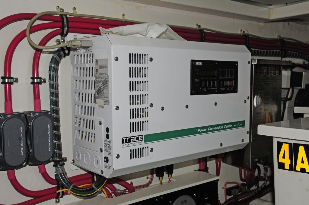
Magnum MMS1012G Inverter Charger
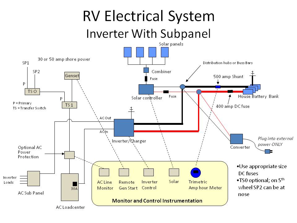
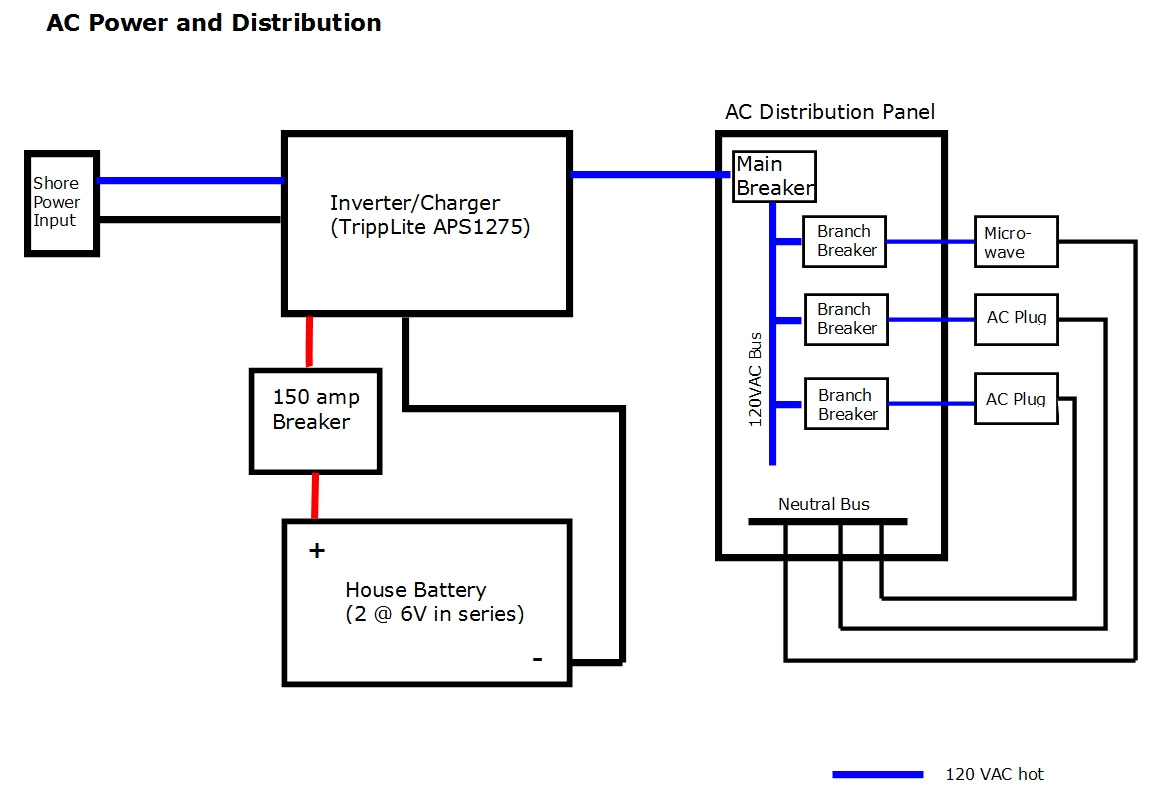
Camper Wiring Diagram w/ 3000w Inverter ... - EXPLORIST.life Dec 17, 2021 · This DIY camper solar wiring diagram and parts list is perfect for ground-up electrical installs into campervans, skoolies, or expedition vehicles. This system is most suitable for systems that do not have a pre-existing house electrical system installed. This diagram features: 2000W Inverter Charger; 200+ Amp Hours of Battery Storage Capacity
How to Install Shore Power in a Campervan Electrical System
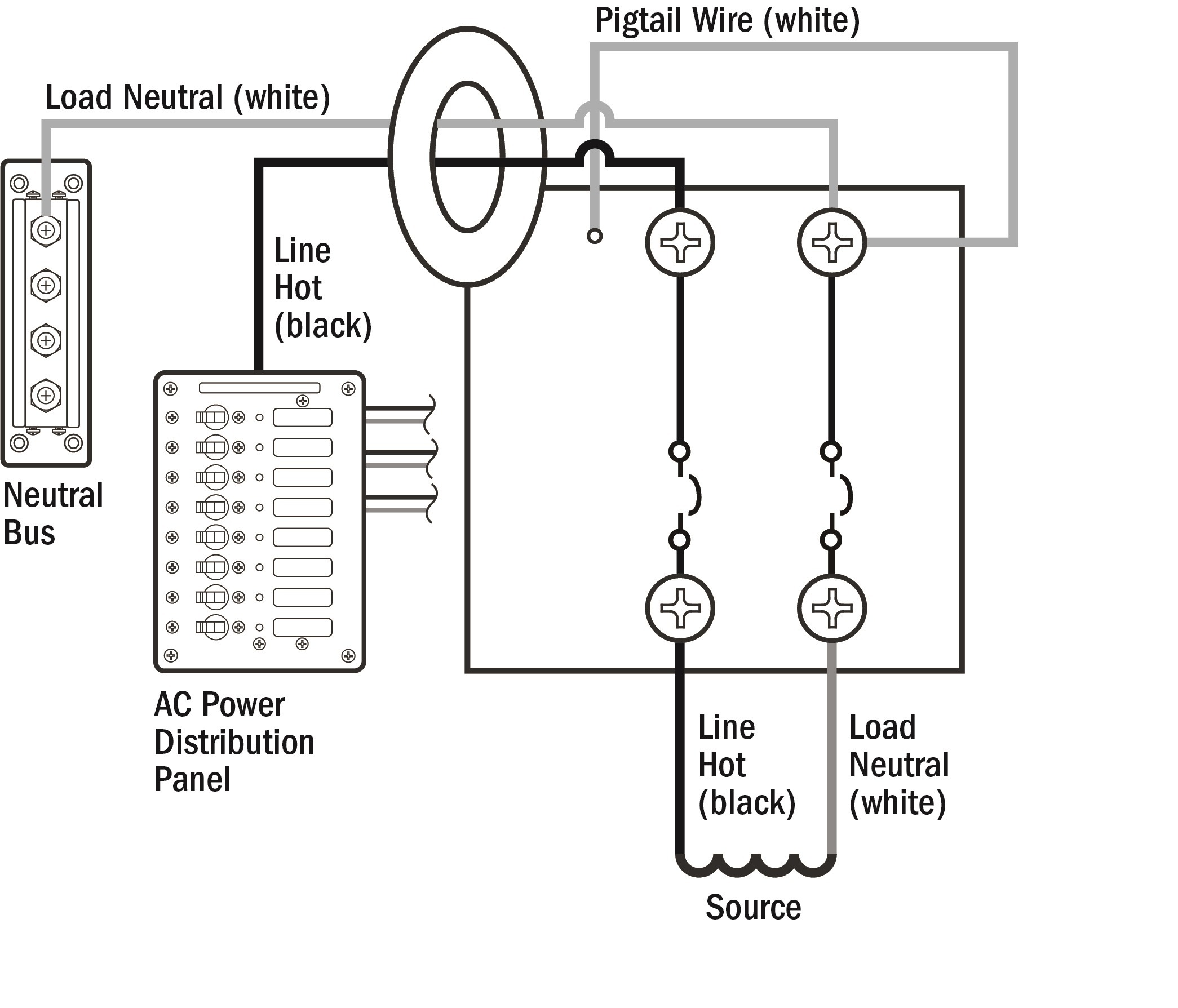
Shore Power Plug Wiring Diagram - U Wiring Shore power plug wiring diagram. Generally the circuit breaker for the RV shore power is located at the pedestal you plug into. YStill larger yachts may use a 50 ampere or 100 ampere 125250 volt system Fig. The shore power cord has a male plug on both ends.
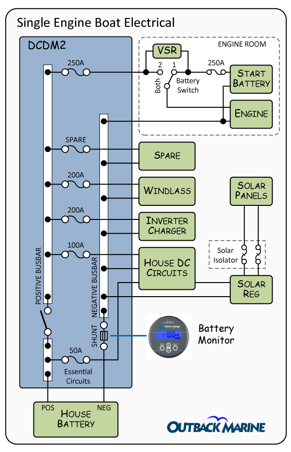
Boat and Yacht Electrical Systems Fundamental Boat Electrical ...
Electrical Wiring Installation Diagrams & Tutorials - Home ... Basic Electrical Home Wiring Diagrams & Tutorials UPS / Inverter Wiring Diagrams & Connection Solar Panel Wiring & Installation Diagrams Batteries Wiring Connections and Diagrams Single Phase & Three Phase Wiring Diagrams (1-Phase & 3-Phase Wiring)Three Phase Motor Power & Control Wiring Diagrams

Inverter Installation | Cruising World
ABYC Cable & Wire Color Codes for Boat & Marine Wiring An insulated electrical wire and cable used in marine (boat, ship, yacht & vessels etc) for electrical wiring connection between different equipment and devices (such as switchboard and general circuits) is known as a marine wire or boat cable.

DIY Shore Power | West Marine
Interactive Wiring Diagram For Camper Van, Skoolie, RV ... Feb 27, 2022 · Here is an interactive version of our wiring diagram for camper van, skoolie, RV, etc. ... 6/3 AWG Triplex AC Marine Wire: Between inverter/charger & AC distribution panel: 1: View: 16: Lugs, 6 AWG Cable, #10: Connect to distribution panel (Pack of 10) 1: View: 17: 120V AC Wall Outlet: GFCI, 20A: 1:
Wiring Diagrams & Literature for Pro Charge Ultra Marine ...
Wiring Schematics - Marine Power USA Wiring Schematics Distributor Kit Wiring Diagram J1939 to NEMA2000 Wiring MEFI 4 MEFI 4 Engine Controls Schematic 4.3L - 5.7L MEFI 4 ECM Circuit Board Layout (5.7-6.0-8.1L) MEFI 4 Engine Controls Schematic 6.0L MEFI 4 ECM Engine Wiring Diagram 8.1L 5.7L Wiring Harness Schematic (472605) MEFI 5 MEFI 5 Engine Controls Schematic 6.0L MEFI 5...

Is It Grounded or Bonded? - American Boat and Yacht Council
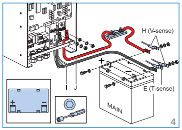
Sailboat Wiring Diagram for Xantrex ... - AC DC Marine Inc Sailboat Wiring Diagram for Xantrex Echo-Charge. Xantrex' digital echo~charge (part # 82-0123-01) is designed to charge auxiliary or starting batteries from an inverter/charger or other charging source with limited voltage drop. The Xantrex echo~charge detects when the house battery bank is being charged and directs a portion of the charge ...

onebox_schematic_large.gif (GIF-Grafik, 1000 × 640 Pixel ...
Marine Power Inverter Wiring Diagram | Trailer wiring ... Marine Power Inverter Wiring Diagram. L. LIUJINGYI. 1 follower. Iphone 6 Silver. Lowe Boats. Auto Test. Trailer Wiring Diagram. Boat Wiring. Zen Design. Boat Trailer. Electric Shock ... Wiring Diagram. I'm working on the 12 volt DC wiring design. The ACR (Automatic Charging Relay) makes the battery charging automatic. ...
Off grid solar power system on an RV (Recreational Vehicle ...
Inverter Installation - Cruising World Inverters electronically convert the power from 12- or 24-volt DC batteries to 120- or 240-volt AC current (the same as shore power or household electricity, albeit with lower capacity). Most inverters are also capable of reverse operation to create battery voltage from the power derived from either a shore-power connection or a generator.
Inverter Installations; What You Need to Know | Steve D ...
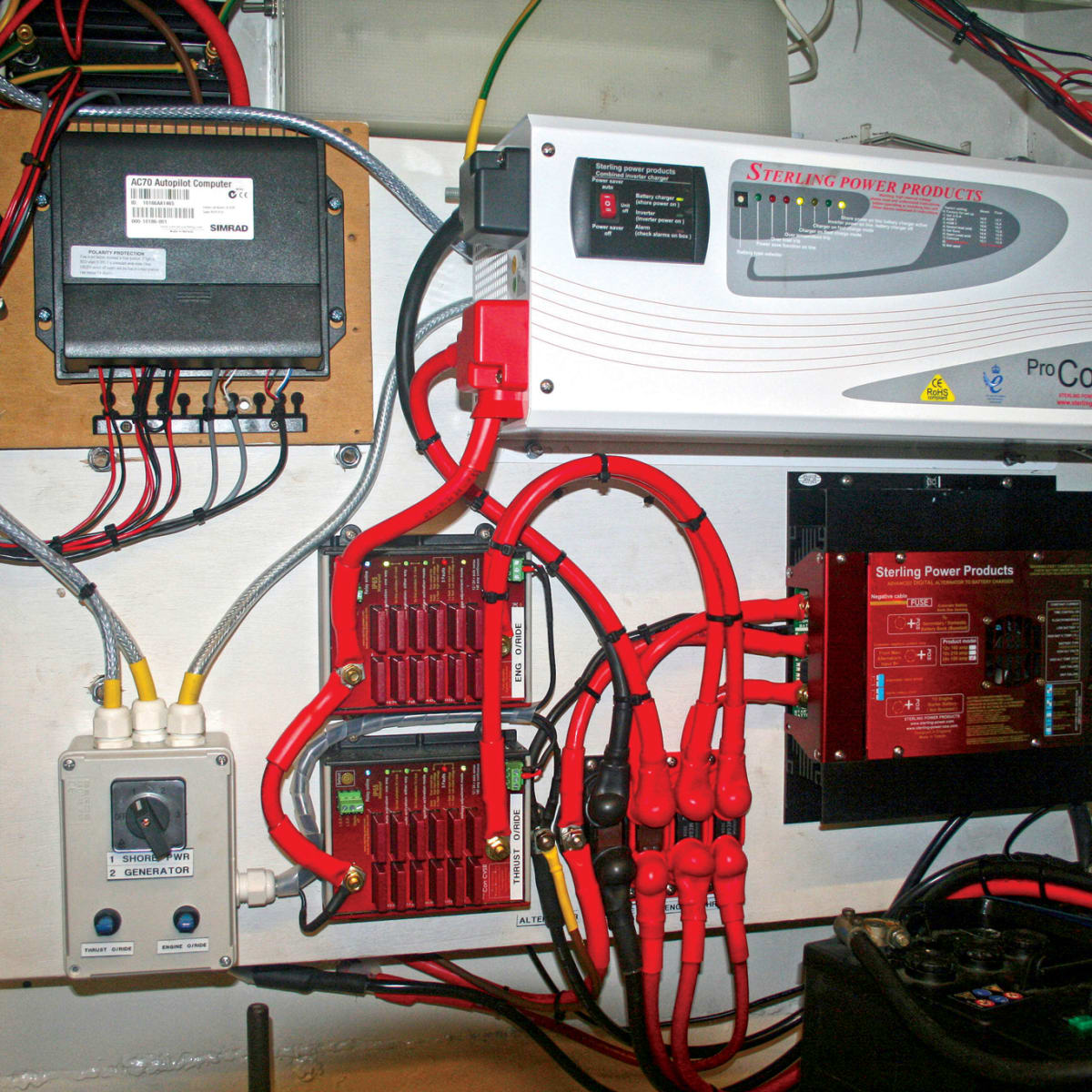
DC Boat Wiring for an Inverter/Charger Installation - YouTube Jeff discusses the importance of wiring on an inverter installation.Sign up for the PYS Newsletter: Jef...
Boat Building Standards | Basic Electricity | Wiring Your Boat
Marine Inverter Charger Wiring Diagram - Free Wiring Diagram Assortment of marine inverter charger wiring diagram. A wiring diagram is a streamlined traditional photographic representation of an electric circuit. It reveals the elements of the circuit as streamlined forms, and also the power and also signal links in between the gadgets.
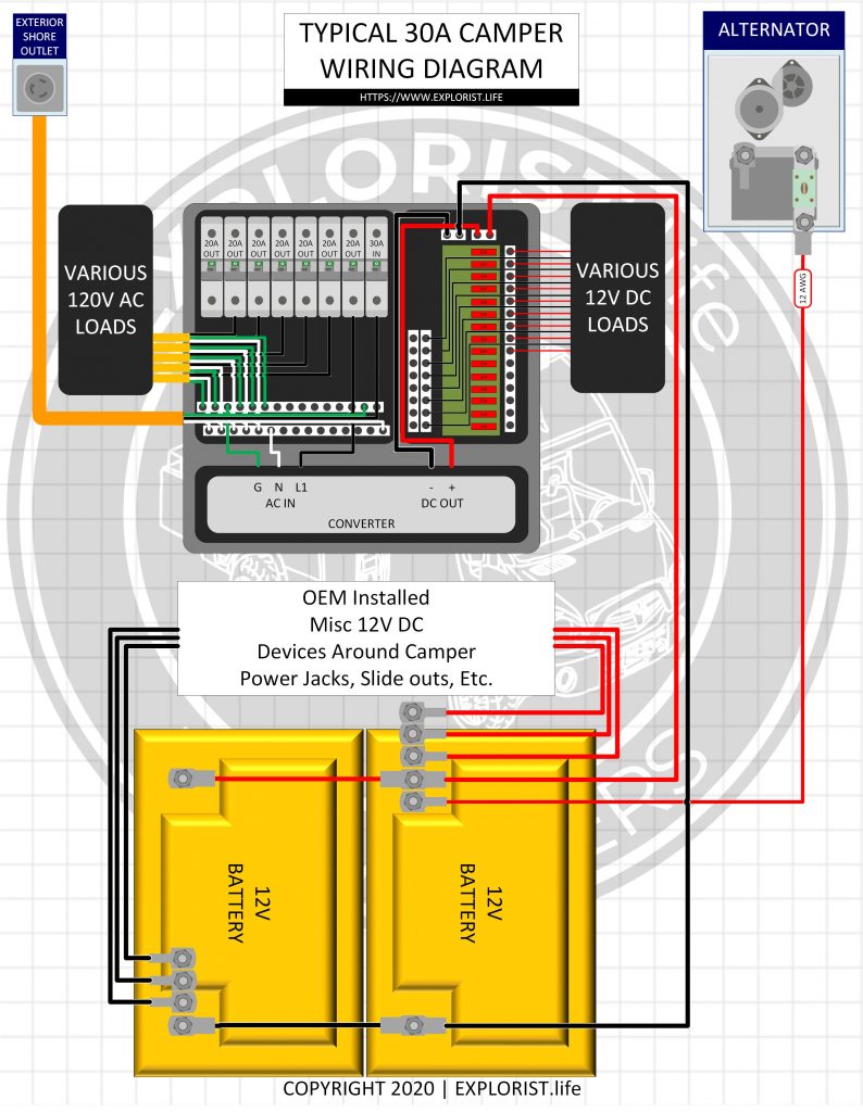
30A OEM RV Solar Retrofit Wiring Diagram – EXPLORIST.life
Camper Van Electrical Design with Detailed Wiring Diagram Nov 05, 2021 · The diagram above outlines in the most simplistic terms, my camper van electrical design. ... Automatically Create Your Bespoke Campervan Wiring Diagram. Includes 110v & 240v, solar, B2B, batteries, inverters, 12v & 24v systems, wire gauges in AWG & mm² & much more! ... They’re all marine grade construction. Automatic Multi-Stage Leisure ...
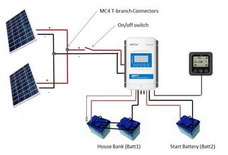
MPPT Dual Output Solar Panel Charge Controller - Marine Solar ...
3 Biggest mistakes when installing an inverter Inverters when installed correctly will provide endless years of energy conversion providing the needed AC power for your appliances and electronics.. Here are 3 of the biggest mistakes typically made during inverter installation: 1) WIRE SIZE - The DC connecting wires from the inverter to the battery bank. It is always best to get the inverter as close to the battery bank as possible (min ...

Upgrading inverter - Electrical Systems - Bill D's Monacoers
Beginners Guide With Diagrams - New Wire Marine You should use marine grade primary wire for this. This is sometimes a long wiring run on a boat. Plus these two conductors will carry the current of all your electrical loads combined, so they are typically fairly beefy cables. Even a small boat (3-5 loads) we'd recommend at least 12AWG wire for this.

RV Inverter Wiring Diagram (RV Electricity Explained ...
Rv Wiring Diagram With Generator - Irish Connections Installation Manual. Rv inverter wiring diagram electricity 12 volt dc 120 400 watt solar panel multiplus charger whisperwatt dac 7000ss sel generator 30a oem retrofit schematic vintage of the pump controller technical second power inlet off grid energy page set sheet damon update added mod diy diagrams for campers system not working a onan gen white board fuel voltage source electrical ...
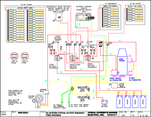
Ocean Currents Marine Electric
Inverter Installations: A Do-It-Yourself Guide | Pacific ... The chassis ground protects both the AC and DC wires (and the green earth wire protects the AC ground). Therefore the wire connection must be equal to or one size smaller than the largest wire connected to the inverter. For instance, a 2,000-watt inverter with a 2/0 wire connection needs a 2/0 or 1/0 chassis ground connection.
Know-how: Inverter, Charger Combos Offshore - Sail Magazine
Marine Inverter Charger Wiring Diagram - Wiring View And ... Inverter Charger Wiring Cruisers Sailing Forums. Marine schematics inverter charger combos offs battery chargers installation cruising world install a multiplus magnum rd2212 ms4448pae power 50 120v ve bus wiring 12v bank for best solar and neutral installations what you need off grid energy system cruisers diy camper van electrical diagram sig 240 boat talk chaparral boats pacific yacht ...

Wiring 12v battery bank for best efficiency — northernarizona ...
Inverter Wiring Diagram For House - The Wiring Wiring Diagram for Inverter Charger Best Marine Inverter Charger. A junction box out at the PV panel array is used to make the connection from the first micro-inverter to the wiring that goes to the house. Related Electrical Wiring Tutorial: Wiring Diagram of Solar Panel with Battery, Inverter, Charge controller and Loads.
Shocking News About Inverter/Charger Installations!
Wiring a Marine Solar System - Marine Solar Panels ... Oct 13, 2015 · This can appear to be a daunting task for those new to the world of solar but it is actually quite easy and straight forward. In this blog I will walk you through the wiring process for our dual output controller step by step. First, the definition of a few terms: * MC4 Connector - A water proof connector used in solar wiring. Most solar panels ...
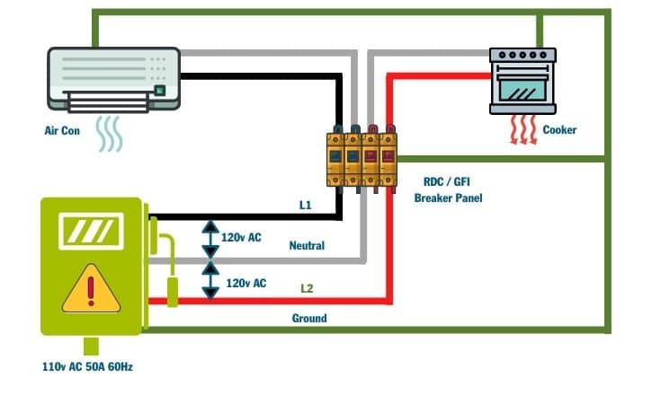
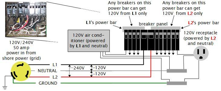
GFCI and ELCI breakers can be confounding, but heed their ...
How to Connect Batteries in Parallel with Power Inverter ... Connect multiple batteries in parallel with your power inverter, solar hybrid inverter or UPS to increase its backup. If you own a single battery inverter, you can connect more batteries in parallel as overall voltage of pack will remain the same while capacity multiplies. Make sure that your power inverter could afford charging several parallel connecting batteries at a time. If charger is ...
Last updated
How to Wire an Inverter in an RV [Schematics in PDF ... In the above diagram, three batteries are connected in parallel to each other and power up the inverter's DC terminals. A fuse box is installed on the positive (red) wire. If we connect high capacity and a greater number of batteries to the battery bank, then the time for which we can take power from the batteries is increased.

Critique my wiring diagram? - Page 3 - Cruisers & Sailing Forums
PDF OWNER'S MANUAL - Xantrex Part No. 90-0113-00 Fdmman2.p65 2/98 OWNER'S MANUAL FREEDOM COMBI TM INVERTER/CHARGERS FREEDOM MODELS 10, 15, 20, 25 ® A Valley Forge Company UL
Boat Building Standards | Basic Electricity | Wiring Your Boat
Inverter Installations; What You Need to Know | Steve D ... If you are considering having an inverter installed, have the work carried out by an ABYC certified marine electrician, or at least by an electrician or yard that is a member of ABYC. Tell the technician you want to be sure it complies with sections E-11 'AC and DC Electrical Systems', and section A-3 'Battery Chargers and Inverters'.

Inverters On Boats | Cruising Aboard Monk36 Trawler Sanctuary

Solar Power - Down to Earth Homesteaders
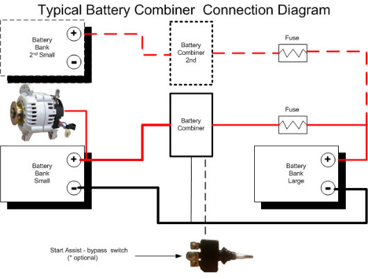
Battery Combiners - e Marine Systems

RV Inverter Wiring Diagram (RV Electricity Explained ...

Interactive Wiring Diagram For Camper Van, Skoolie, RV, etc ...
ProMaster DIY Camper Van Conversion -- Electrical
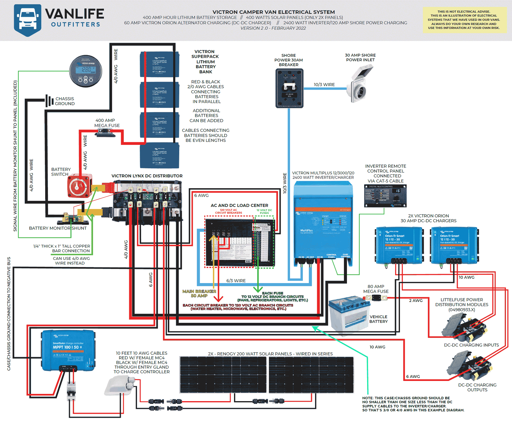
DIY Camper Van Electrical Diagram - Updated September 2020

Boat Show 2018 - DIY Marine Electrical Connections
Inverter DC negative wiring - The Hull Truth - Boating and ...
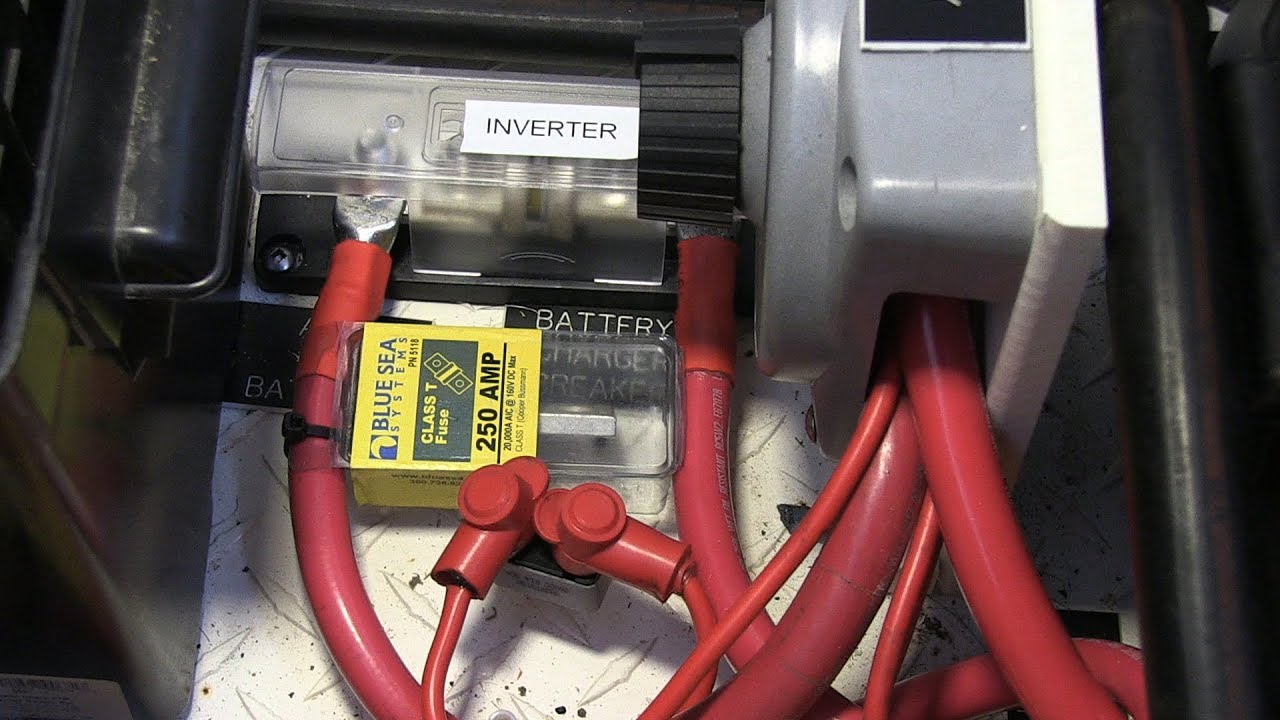
DC Boat Wiring for an Inverter/Charger Installation
Boat Show 2019 - How To - Choosing & Installing An Inverter ...
How to Install a MultiPlus Inverter/Charger? - Victron Energy

Inverters On Boats | Cruising Aboard Monk36 Trawler Sanctuary
0 Response to "37 marine inverter wiring diagram"
Post a Comment