36 end of line resistor wiring diagram
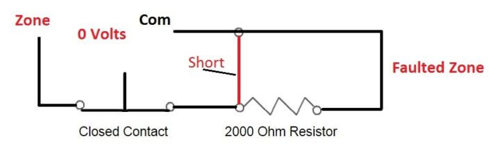
PDF Copley Controls Corp | 1.4.3: Regen Resistor (J3) Wiring Regen Resistor Sizing and Configuration. Xenus Regeneration Guide. 1.4: Regen Circuit Wiring. 5 Resistance (line-to-line) of the motor windings. A.1.1.2. For rotary motor applications, gather this additional information: 1 Load I2 = Shaft speed at the end of deceleration in radians per second. End of Line Resistors: Resistor Usage in Alarm Systems What are end of line (EOL) resistors? What is their purpose and how do you use them? We hope to answer all of your questions in our video below! So what our resistor's going to do is actually supervise the wiring. So you would be able to tell, for instance, if you have a short in your wiring.
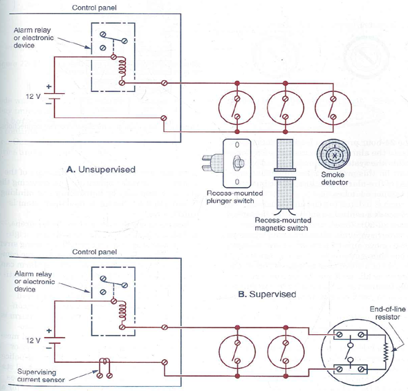
PDF Microsoft Word - S4090-0010-8.doc | Wiring Requirements End-of-Line Resistor For Class B NAC; 10 kW, 1/2 W; 4081-9008. Wiring Distance Information Reference. 2. This reference wiring diagram shows a Class A signal riser providing input to each Signal IAM, and a Class A IDNet signaling line circuit (SLC) for control of the Signal IAMs.
End of line resistor wiring diagram
6.2 Resistors in Series and Parallel - Introduction to Electricity... Resistors are in parallel when one end of all the resistors are connected by a continuous wire of negligible resistance and the other end of all One implication of this last example is that resistance in wires reduces the current and power delivered to a resistor. If wire resistance is relatively large, as... Variable Resistor - Working, Construction, Characteristics... A variable resistor is the type of resistor which changes the flow of current in a controlled manner by offering a wide range of resistances. As the resistance increases in the variable resistor the current through the circuit decreases and vice versa. Double End Of Line Resistor Wiring Diagram... | ManualsLib Pyronix ATLAS 4 Manual Online: double end of line resistor wiring diagram, Telephone Connections, Powering Up The Panel. The 2k2 resistor should be installed in the last detector in series. to protect all the zone tamper wiring. Up to ten sensors or door contacts may be wired on each zone.
End of line resistor wiring diagram. Electrical Drawings and Schematics Overview | Wiring Diagram Also called one-line diagrams, these drawings show the flow of electrical power or the course of Components that are commonly found on schematic diagrams include resistors, capacitors Wiring diagrams should identify all equipment parts, devices, and terminal strips with their appropriate... Wiring Diagram - A Comprehensive Guide | EdrawMax Online Block Diagram, Logic Diagram, Single Line Diagram, etc. Most use for. A wiring diagram is mainly used in motor control installations and designing Resistor - The resistor shows the restriction to the flow of current. It is used along with a capacitor in a timing circuit. Wire and Connection - Wire and... Wiring Diagram for double End-of-Line resistor wiring. Double End-of-Line Resistor. This article will explore each of three zone wiring types. Note: this article does not discuss wiring for fire alarm circuits, which are wired Normally Open Single End-of-Line Resistor. This is the default circuit configuration. As the name implies, it uses only one EOL. Resistor - Wikipedia A resistor is a passive two-terminal electrical component that implements electrical resistance as a circuit element. In electronic circuits, resistors are used to reduce current flow, adjust signal levels, to divide voltages, bias active elements, and terminate transmission lines, among other uses.
End Of Line Resistor Wiring Diagram For Your Needs Read wiring diagrams from negative to positive and redraw the circuit being a straight collection. All circuits are the same ~ voltage, ground, solitary component, and changes. End Of Line Resistor Wiring Diagram Source: . How Variable Resistors Work - Circuit Basics | Wiring a Potentiometer Variable resistors are resistors that change resistance from zero to a certain maximum value. Wire the second terminal to the circuit's output to create the potentiometer's input. Potentiometer Schematic Symbol. Referring to the diagram above, Pins 1 and 3 are the ends of the resistor, while... What's EOL end of line resistor ? | Technology News End of line resistors (EOLR) are resistors of a specified value that are used to terminate protective loops or zones. The purpose of EOLR's is to allow the control panel to supervise the field wiring for open or short circuit conditions. How the alarm responds to each depends on the panel as well as... End of Line Resistors (EOLRs) in Fire & Gas Systems End of line resistors (EOLR) are resistors, of a known value, that are used to terminate protective loops or zones, such as those found in Fire and Gas (F&G) systems and some The purpose of EOLR's is to allow the control system to supervise the field wiring for open or short circuit conditions.
What is an end of line resistor? - Quora The End of Line Resistor is needed to prevent reflections. On the other hand, if we placed some resistor along the path of the wires, now the total opposition of the circuit is the equivalent series resistance of the battery plus the resistance of the resistor we added. Best Of End Of Line Resistor Wiring Diagram | Wiring Diagram Image Harbor Breeze Ceiling Fan Wiring Diagram Beautiful End Line Resistor from end of line resistor wiring diagram , source:crissnetonline.com. Think about graphic over? is actually in which awesome???. if you think maybe consequently, I'l t explain to you several graphic yet again down... Resistor & Types of Resistors - Fixed, Variable, Linear & Non-Linear Variable Resistors. Potentiometers. Rheostats. Trimmers. Non Linear Resistors. Thermistors. There are two conductor wires on the both ends of the resistor for easy connectivity in the circuit via soldering. When voltage increases (due to lighting or line faults) across a connected sensitive... PDF HCA Series I&O Manual Wire must NOT enter the bottom of the cabinet, since this area is intended for batteries only. Refer to figure 3.5 for the AC power wiring diagram. 1. Route the power cable into the cabinet via a left side Observe the polarity of the wiring and the placement of the 10kW end of line (EOL) resistor located...
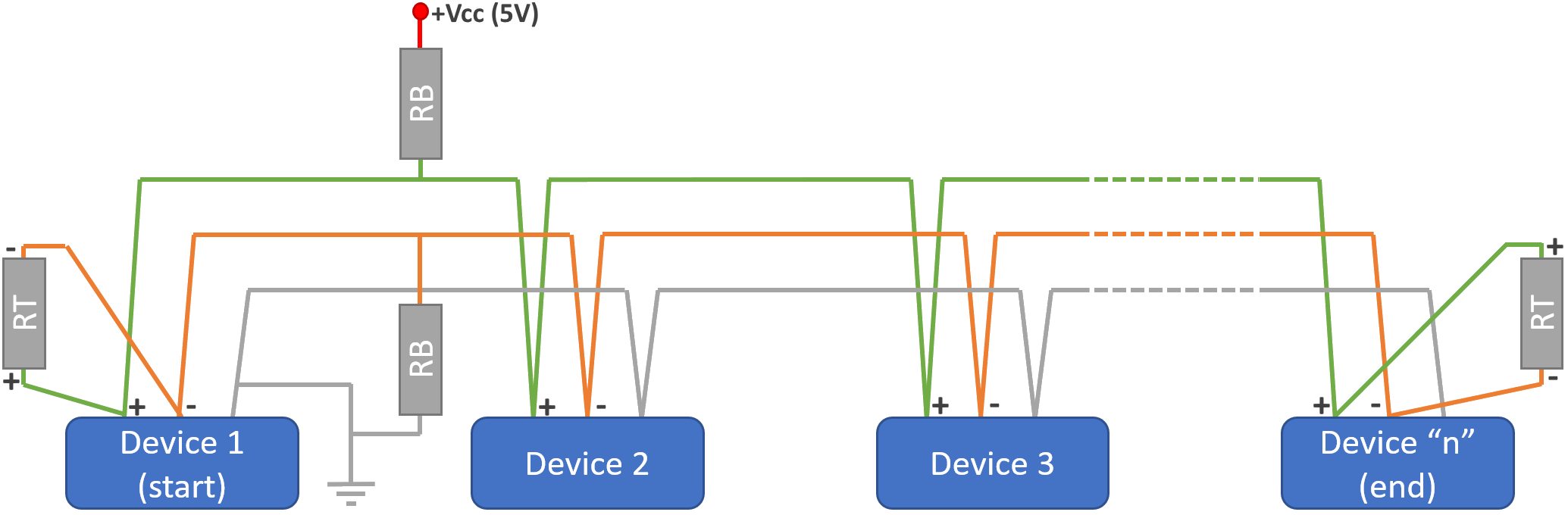
Why and how do I use Bias resistors and Termination resistors ...
Garmin Wiring Fundamentals Series - End-of-Line... - YouTube Garmin Wiring Fundamentals Series - End-of-Line Terminating Resistor Wiring. Смотреть позже. Поделиться.
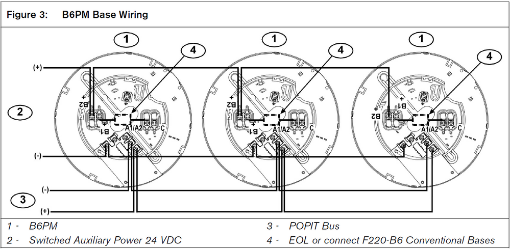
How to Wire the F220 Popit Bases
PDF Wiring Diagram Book WIRING DIAGRAM A wiring diagram shows, as closely as possible, the actual location of all component parts of the device. The open terminals (marked by an open circle) and arrows represent connections made by the user. Since wiring connections and terminal markings are shown, this type...
Why we use End of Line (EOL) Resistor in Fire and Gas System ?
Why we use End of Line (EOL) Resistor in Fire and Gas System ? The End-of-Line Resistor used in fire alarm systems and security systems may look the same as a Terminating Resistor, however the function of the End-of-Line Resistor is completely different. It's important to understand that the "signals" used in fire alarm systems are DC, either on or off, not AC...
How to wire EC-FX-NH3 to 301C?
Resistors in Series and Parallel | Physics Resistors are in parallel when each resistor is connected directly to the voltage source by connecting wires having negligible resistance. Figure 5 shows the resistors from the previous two examples wired in a different way—a combination of series and parallel.

Connecting Low-Voltage Smoke Detectors : Konnected Help & Support
Wiring Diagram - Everything You Need to Know About Wiring Diagram Unlike a pictorial diagram, a wiring diagram uses abstract or simplified shapes and lines to show components. A resistor will be represented with a series of squiggles symbolizing the restriction of current flow. An antenna is a straight line with three small lines branching off at its end, much like a...

Installation Instructions: SH-449CSTE Smoke Detector
Building Simple Resistor Circuits | Series And Parallel Circuits Jumper wires with "alligator" style spring clips at each end provide a safe and convenient method of electrically joining components together. If we wanted to build a simple series circuit with one battery and three resistors, the same "point-to-point" construction technique using jumper wires could be...

20 Alarm system ideas | alarm system, fire alarm system, alarm
Matrix 6 816 | 2.6.3 Single End of Line (SEOL) Resistor Wiring Matrix 6/816 Installation Manual. 2.6.3 Single End of Line (SEOL) Resistor Wiring. NOTE: Any unused zones should be linked out using a 4k7O resistor.
Do's and Don'ts BACnet Wiring (Part 2 of 3)
Light Dependent Resistor : Circuit Diagram, Types, Working... Light Dependent Resistor Circuit. The circuit of LDR is an electronic circuit built with LDR, relay, Darlington pair, diode, & resistors shown in the below circuit diagram. LDRs are not linear devices and their sensitivity changes through the light's wavelength which drops on them.
Wiring Puzzle Solved – Restoration of NNF 10H
Resistors in AC Circuits - Impedance of a Resistor Electronics Tutorial about Resistors in AC Circuits and the Impedance of a Resistor in an AC Circuit due to the frequency of a sinusoidal waveform. Also the schematic symbol used for defining an AC voltage source is that of a "wavy" line as opposed to a battery symbol for DC and this is shown below.
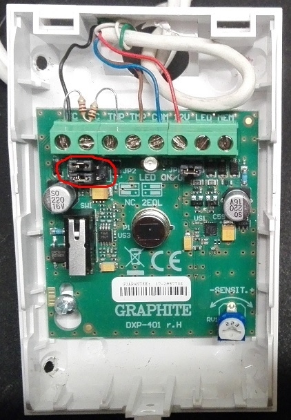
How to connect any detector to the alarm control panel - guide
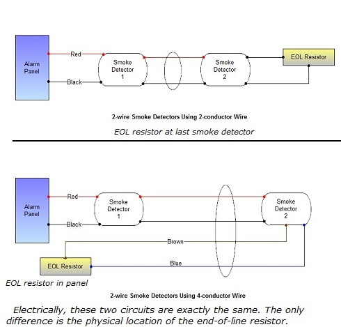
Where Do End Of Line Resistors Go? | Forum "End of the line, or EOL. In the panel is just lazy." "If you understand the theory as to why a resister is used, you'd get why it's placed at the contact." "In NYC traditionally you run a 4-wire and put the resistor back in the box... but electrically still at the end of the line. Everywhere else, it should be at...

☑ End Of Line Resistor For Alarms
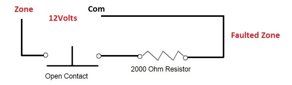
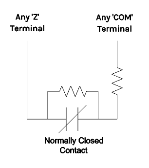
END OF LINE RESISTOR installation The end of line resistors (EOLR for short) are resistors designed for a pre-determined valued and used to control protected zones. There is a multitude of ways wires can be shorted or affected in a way that might not be perceivable without an end of line resistor.

Is there a 67 911 engine compartment wiring diagram online?
End Of Line Resistor Wiring Diagram - Free Diagram For Student Fire alarm wiring schematic end of line resistor color code detector fire alarm wiring diagram rj 11 telephone jack wiring diagram fire alarm eol If youre using 2 conductor wire connect the end of line resistor eolr to the terminals as shown. End of line resistors for those systems are installed here.
How to Wire Security Alarm Zones | TremTech Blog
Double End Of Line Resistor Wiring Diagram... | ManualsLib Pyronix ATLAS 4 Manual Online: double end of line resistor wiring diagram, Telephone Connections, Powering Up The Panel. The 2k2 resistor should be installed in the last detector in series. to protect all the zone tamper wiring. Up to ten sensors or door contacts may be wired on each zone.

Typical One-line Fire Alarm system Wiring Diagram - Maple Armor
Variable Resistor - Working, Construction, Characteristics... A variable resistor is the type of resistor which changes the flow of current in a controlled manner by offering a wide range of resistances. As the resistance increases in the variable resistor the current through the circuit decreases and vice versa.
Refer to Figure 22-28. Assume the end-of line resistor of ...
6.2 Resistors in Series and Parallel - Introduction to Electricity... Resistors are in parallel when one end of all the resistors are connected by a continuous wire of negligible resistance and the other end of all One implication of this last example is that resistance in wires reduces the current and power delivered to a resistor. If wire resistance is relatively large, as...
Why we use End of Line (EOL) Resistor in Fire and Gas System ?
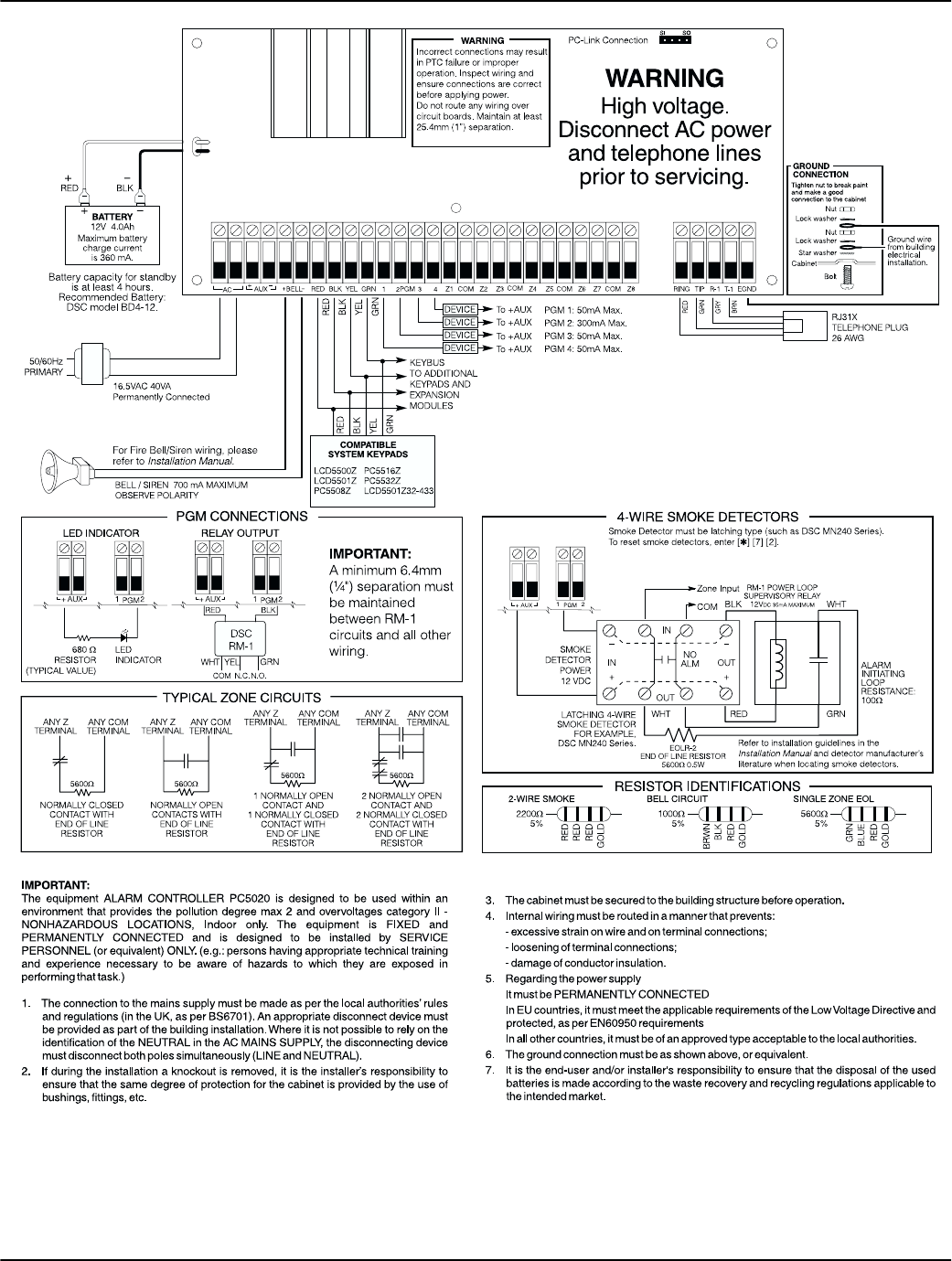
PC5005 V3 2 Int Im 29005954 R001 Main Text V3.2 Installation ...
ESIM364 Alarm system User Manual Part 1 ELDES

How to read wiring diagrams | Ross-Tech Forums
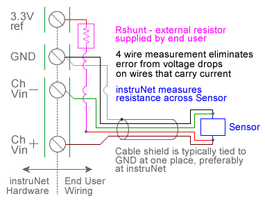
RTD Temperature Measurement with USB Data Acquisition ...
INSTALLATION MANUAL
Neue 8 zone Brandmelderzentrale Nicht adressierbare ...

LP-200012UL Installation Instructions

Smoke Detector Installation Guide

Wiring diagram 2 Mitsubishi Electric A Series CPU Direct ...
Apparatus and method for detection and adaption to an end-of ...
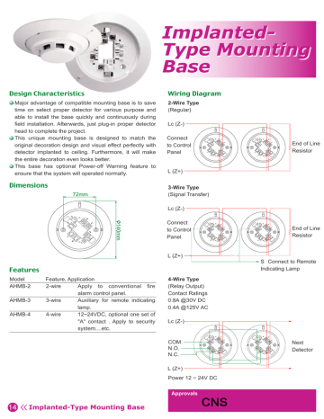
AHMB-2,3,4 | Manualzz

Infinity Control Panel Quick Start Guide - Discount Fire Supplies
Electrical Wiring -
Connecting 2 Wire Smoke Detectors

Copper-Covered HeNe Laser Power Supply Brick Wiring ...
How to connect any detector to the alarm control panel - guide

INTRUSION ALARM TECHNOLOGY - ppt download

Wiring diagram of test of single-ended grounding of cable ...

What is Conventional Fire Alarm System? Wiring Diagram - ETechnoG

conventional head removal - Printable Version
0 Response to "36 end of line resistor wiring diagram"
Post a Comment