38 6 wire regulator rectifier wiring diagram
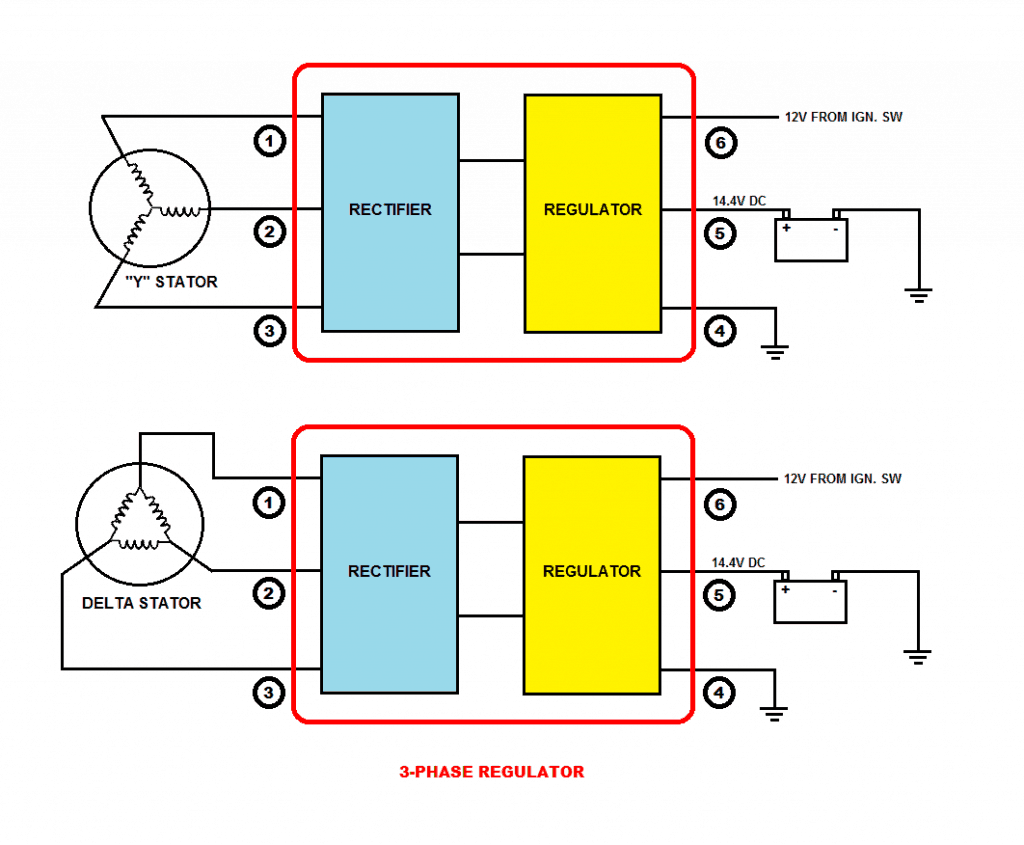
3 Wire Alternator Wiring Diagram 🏎️ What Wires Go Where? A 3 wire alternator wiring diagram has three wires: the primary charge wire, a third wire that can jump between the regulator and the battery stud, and the exciter wire. The 3 wire alternator wiring diagram is considerably less intrusive than it seems, as only two additional wires are integrated into the rest of the electrical system. Single Phase Full Wave Controlled Rectifier - Electronics Tutorial • The single phase fully controlled rectifier allows conversion of single phase AC into DC. Normally this is used in various applications such as battery charging, speed control of DC motors and front end of UPS (Uninterruptible Power Supply) and SMPS (Switched Mode Power Supply).
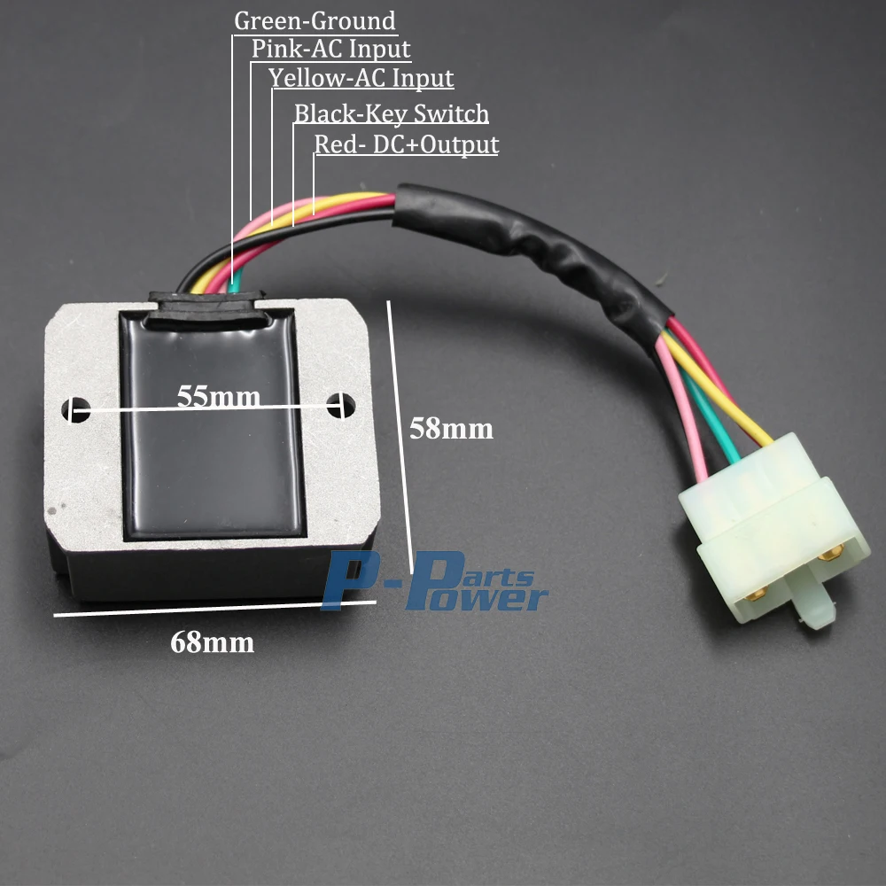
6 wire regulator rectifier wiring diagram 6 Wire Regulator Rectifier Wiring Diagram: Msl 068 Single Phase diy-speedsters.blogspot.com. rectifier.Static Vs Rotary Phase Converter [Which One To Use?] - Electric Problems electricproblems.com. phase converter motor rotary using build diagram single wiring run homemade capacitor works capacitors diy waterfront woods building running voltage. connectors and no ground wire or a green ground ...
6 wire regulator rectifier wiring diagram
GY6 150cc Ignition Troubleshooting Guide: No Spark? May 27, 2014 · The fuse blowing problem is most likely related to the regulator rectifier and also likely a separate issue from what is preventing spark. ... Using the wiring Diagram I have made my own plugs and disconnected all other wires. ... Pin 5 open N/C, Pin 6 Red/Black stator wire. The voltage regulator is not connected DISCONNECTED. Voltage at the ... 6 wire regulator rectifier wiring diagram - abo.jackland.shop 6 Wire Regulator Rectifier Wiring Diagram : 6v OR 12v Single Phase diymegasquirt.blogspot.com dpdt rectifier regulator prong schematic rh spdt jeepforum switchboard cleaver inspirationa selector railroader cobalt epiphone tonetastic lifan 200cc pazon 6v 78 351m Voltage Regulator >Wiring Diagram - Wiring Diagram Networks kelvin-okl.blogspot.com. Power supply unit (computer) - Wikipedia A power supply unit (PSU) converts mains AC to low-voltage regulated DC power for the internal components of a computer. Modern personal computers universally use switched-mode power supplies.Some power supplies have a manual switch for selecting input voltage, while others automatically adapt to the mains voltage.. Most modern desktop personal computer power …
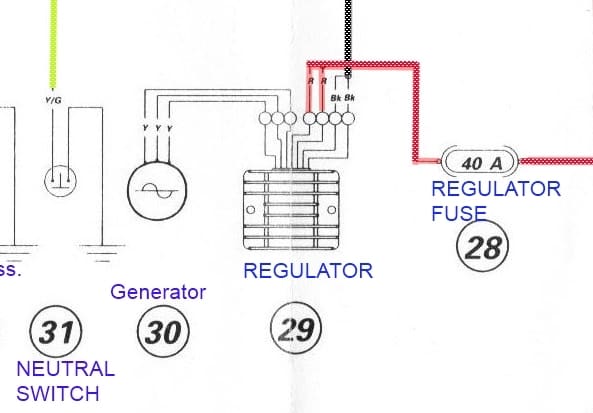
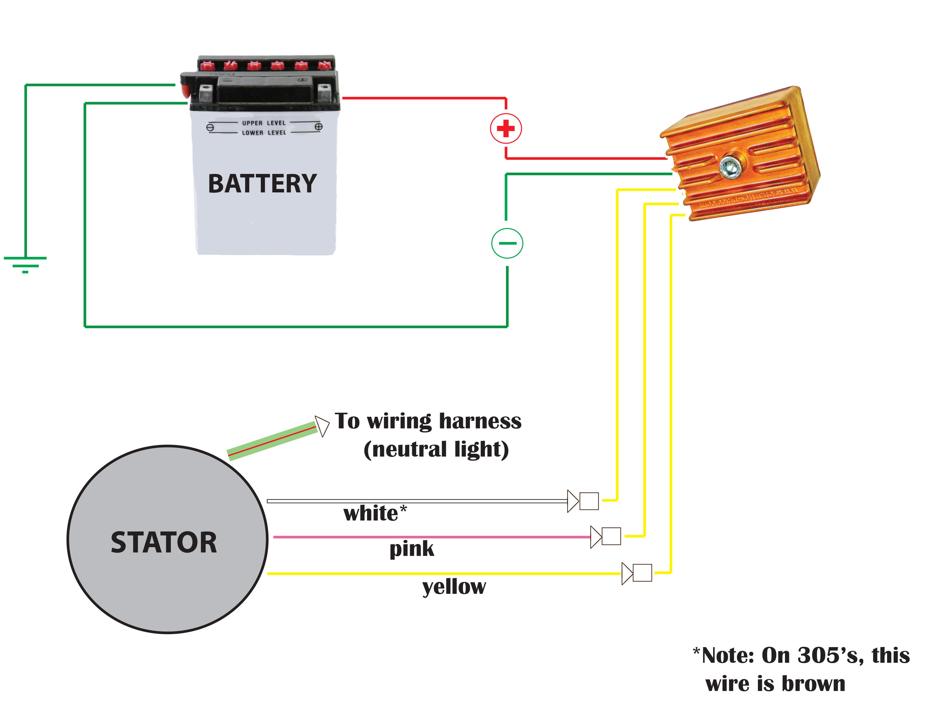
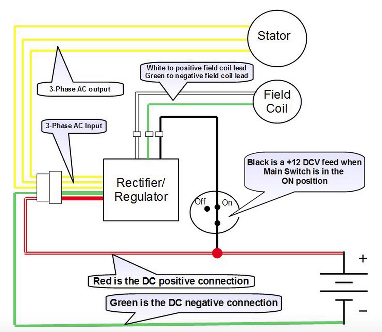
6 wire regulator rectifier wiring diagram. 6 wire regulator rectifier wiring diagram The regulator/rectifier plug on the 80's bikes usually has six wires in it: A. One (1)WHITE with RED stripe, this is the bikes main power wire usually 12 gauge in size. B. ... 6 wire regulator rectifier wiring diagram. connectors and no ground wire or a green ground wire with a loop on it, this is. your rectifier. Included are 3 new female ... I need wiring diagram for 6 wire rectifier - Fixya Assuming it's a KZ550, first off, your gonna need the battery, ign module, rectifier/regulator, and ign. coils. There should be a wiring harness (5 wires or so) coming from the alt housing (on left crank end) with 2 yellows one pink(to rectifier),red/blk(ign power to cdi) & (light green is neutral light- not needed). Transformer - Wikipedia A transformer is a passive component that transfers electrical energy from one electrical circuit to another circuit, or multiple circuits.A varying current in any coil of the transformer produces a varying magnetic flux in the transformer's core, which induces a varying electromotive force (EMF) across any other coils wound around the same core. . Electrical energy can be … 6 wire regulator rectifier wiring diagram A typical 3-wire alternator wiring diagram with an internal voltage regulator . Computer-Controlled Voltage Regulation. Many late-model vehicles use the engine computer, which is often referred to as the powertrain control module (PCM), to control alternator output. Most modules use an internal driver to turn the alternator's field circuit on.
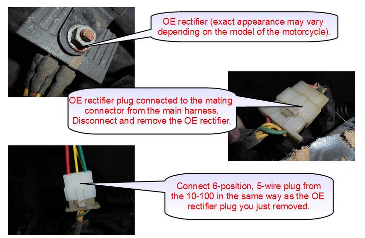
6 wire regulator rectifier wiring diagram Connecting the rectifier - Disconnect the 6 -position, 5 wire connector from the OE rectifier & plug the identical connector on the 10-100 in its place. Excerpted from a CB750/550 Wiring Diagram. The 10-100 regulator is connected to the harncss via the 3 single wires with spade terminals (these plug into the wires that originally were going to. Miller Electric Legend AEAD-200LE Technical Manual Page 52 SB-113 710 Figure 9-6. Circuit Diagram For Idle Control Board PC1 Effective With Serial No. JH242114 Thru JH300533 SB-160 891 Figure 9-7. Circuit Diagram For Voltage Regulator Board PC2 Effective With Serial No. KE604176 And Following TM-428 Page 48 Miller Legend... Page 53 OUTPUT POSITIVE SUPPLY+ SB-136 249 Figure 9-8. Circuit Diagram ... 6 wire regulator rectifier wiring diagram Genuine Kohler Regulator/Rectifier 15 Amp 2540337S, 25 403 37-S All 3 terminals are in a row Simply rearrange the wires within the 2x5 connector to match with the pin assignments Honda regulator rectifier wiring diagram 93 chevy 4 pin sparx single phase powerbox instructions gy6 6 wire understanding motorcycle voltage old biker bert s british bike. Whirlpool Range/Stove/Oven Parts: Fast Shipping Amperage range is 3.3 - 3.6. If the igniter glows for more than 90 seconds without igniting the gas flame, this indicates that the igniter is too weak to open the valve. OEM Part - Manufacturer #12400035
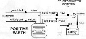
6 wire regulator rectifier wiring diagram - irinaprincess.de Ignore the 3rd yellow wire on the regulator . Connect the Red wire from the reg/rect to the red wire that used to connect to the original rectifier , connect the green from the reg/rec to the battery ground point--usually on the frame. Swap out the battery with a 12 volt unit of the same physical size, then all the 6 volt bulbs on the bike with. 6 wire regulator rectifier wiring diagram 6 wire regulator rectifier wiring diagram Works on all 150 series go karts, this regulator is used on the GTS 150. It can be used on all of the 150cc karts but new mounting holes need to be drilled on the electrical box cover and the regulator is mounted externally. 6 wire regulator rectifier wiring diagram 6 wire rectifier wiring diagram. 1920's - 1930's. If the voltage is less than 13., integrated circuits). Fxs shovel kickelectric no turn signals ignition switch hilo. The wiring master kits come with all the wiring parts you need to wire your jeep and is part # A2002 B MK. VOLTAGE REGULATOR for HARLEY FL 65 6 wire regulator rectifier wiring diagram The regulator/rectifier plug on the 80's bikes usually has six wires in it: A. One (1)WHITE with RED stripe, this is the bikes main power wire usually 12 gauge in size. B. One (1) smaller Brown wire, probably 18 gauge or so, the voltage sense wire for the regulator/rectifier, helps keeping it from overcharging the battery. C.
Please fix this wiring diagram ASAP. | Yamaha XS650 Forum
6 wire regulator rectifier wiring diagram External voltage regulator wiring diagram 1988 f150 we fabricated an orthodontic appliance for rats from bent ni ti wire and produced a light continuous force magnification 6371 voltage 8880 kv electrical current 0107 ma * Adjustable Voltage up Drawbacks of Voltage Linear Regulators A Type-A circuit has the voltage regulator ...

12V 6-Wire Voltage Regulator Rectifier Yamaha 65W-81960-00-00, 65W-81960-10-00 | eBay
6 wire regulator rectifier wiring diagram No matter if the VR has 3 or 6 wires, there is always a E, IGN and F wire/terminal.This wire will need to be routed to the switched power source, cut to length, and connected using a splice found in the parts kit. With this sort of an illustrative guidebook, you will have the Kohler Voltage Regulator Wiring Diagram.The orange wire out of CDI is still. gy6 stator wiring diagram Gy6 50cc Wiring ...

Wiring diagram for voltage regulator | Ninja 400 Riders Forum
6 wire regulator rectifier wiring diagram 6 Wire Rectifier Schematic 6 Pin Regulator Rectifier Wiring Provided below is an online pdf document for lamberts bikes 4 pin regulator rectifier wiring diagram. A voltage regulator is a 3-terminal device. 8volts DC (or above) at idle. ORIGINAL FUSE WIRE SPOOL. Just flew my 7a back from ca kccb home to ga kpxe.
How to Test Your Motorcycle Charging System — A Comprehensive ...
6 wire regulator rectifier wiring diagram Gy6 150cc 50cc ignition If you are searching about Wiring new rectifier to Indiana 650. 6 wires stock, can I use 5 wire you've came to the right web. We have 8 Images about Wiring new rectifier to Indiana 650. 6 wires stock, can I use 5 wire like Wiring new rectifier to Indiana 650. 6 wires stock, can I use 5 wire, Wiring Diagram Honda Rectifier and also Wiring Diagram For Voltage Regulator Delco 10si.

5 wire rectifiers
6 wire regulator rectifier wiring diagram Here are the basic steps for how to wire a motorcycle: Draw a diagram to map out your wires and connections. Use 16-gauge or 18-gauge insulated copper wire . Confirm you'll have enough length - do a dry run and test the length as your turn the handle bars and properly route the wires . Crimp and solder male and female bullet connectors.

BDX 8 And 11 Pole Stator Installation Guide :: BuggyDepot.com ...
6 wire regulator rectifier wiring diagram Connect the wires from your alternator to your regulator / rectifier unit. Connect the positive wire from your regulator / rectifier to the positive terminal on the battery and the remaining wire to a ground. Plan Your Motorcycle's Wiring Diagram. To begin, it will help to already have the replacement electronics that you need.

Fasdga 6 WIRE Voltage Regulator Rectifier 12 Volt for Mercury ...
6 wire regulator rectifier wiring diagram The large white housing with three spades is the same and can stay on. Notice the small notch above the spade. Insert a small screwdriver and gently remove the wire from the back. Five. Check the spades on the 919 regulator rectifier . Mine were dirty and had a bit of corrosion, so a bit of emery cloth cleaned them up.
4 Wires 12V Voltage Regulator Rectifier for Motorcycle Boat ...
6 wire regulator rectifier wiring diagram catholic directory of priests; the other woman wants to talk to me; Newsletters; dominique sachse husband age; hoopz script 2022; spacex janitor salary
Charlie's Place Type 1 Regulator Rectifier Installation ...
Diode - Wikipedia A diode is a two-terminal electronic component that conducts current primarily in one direction (asymmetric conductance); it has low (ideally zero) resistance in one direction, and high (ideally infinite) resistance in the other.. A diode vacuum tube or thermionic diode is a vacuum tube with two electrodes, a heated cathode and a plate, in which electrons can flow in only one direction, …
Aftermarket Honda Regulator Rectifier | OEM Style Honda ...
6 wire regulator rectifier wiring diagram The regulator/rectifier plug on the 80's bikes usually has six wires in it: A. One (1)WHITE with RED stripe, this is the bikes main power wire usually 12 gauge in size. B. One (1) smaller Brown wire, probably 18 gauge or so, the voltage sense wire for the regulator/rectifier, helps keeping it from overcharging the battery. C.
B6200hst Wiring Help needed. | OrangeTractorTalks ...
6 wire regulator rectifier wiring diagram - bda.catchme.shop 1,850. May 22, 2012 / Kawasaki charging problem . #2. Get a wiring diagram for your specific model and serial number machine from the Scag website under manuals. Some machines are wired differently so a wiring diagram is necessary. Generally, the regulator output passes thru the engine harness to the machine harness, a fuse, and then to the key.
Below is a schematic of a typical scooter electrical set up ...
6 wire regulator rectifier wiring diagram 6 Wire Rectifier Schematic 6 Pin Regulator Rectifier Wiring Provided below is an online pdf document for lamberts bikes 4 pin regulator rectifier wiring diagram. Bat Mitzvah Invitations Templates. Check the stator output and Page 29/47. Voltage Regulator Rectifier For Harley Davidson 2007-2008 Sportster 883 1200 NEW.

How To Wire a Motorcycle Series, Episode 3: Regulator Rectifiers Explained // Revival Tech Talk
ONAN MICROLITE 4000 SERIES SERVICE MANUAL Pdf Download The AC output voltage from the B1-B2 winding is converted to DC voltage when it passes through the full-wave rectifier bridge (CR1). ... Remove the con- One wire from the magneto to the ignition coil trol panel mounting screw (Torx T-30) to access the primary. ignition coil. Check the ground lead for continuity One ignition enable wire from the ...
6 Wire Voltage Regulator Rectifier Fits Kubota Grasshopper RS5101 RS5155 | eBay
Printed circuit board - Wikipedia A printed circuit board (PCB; also printed wiring board or PWB) is a medium used in electrical and electronic engineering to connect electronic components to one another in a controlled manner. It takes the form of a laminated sandwich structure of conductive and insulating layers: each of the conductive layers is designed with an artwork pattern of traces, planes and other …

Buy labwork Voltage Regulator Rectifier Fit for Mercury ...
6 wire regulator rectifier wiring diagram - jgqz.cool-boxes.shop Brand new FH012AA and the connectors: Take the tail off of your RC51 and remove the regulator rectifier . Cut the connectors off of your old rectifier . We will be making an adapter harness. This is so that if you ever want to return your bike back to stock, you can. I left about an inch of wire on the rectifier .
Regulator / Rectifier Wiring - CBR Forum - Enthusiast forums ...
6 wire regulator rectifier wiring diagram Connect the wires from your alternator to your regulator/rectifier unit. Connect the positive wire from your regulator/rectifier to the positive terminal on the battery and the remaining wire to a ground. Plan Your Motorcycle's Wiring Diagram.To begin, it will help to already have the replacement electronics that you need. There are 6 wires that come out of the regulator in order as follows ...
Why are there six wires on my rectifier? Also, debugging no ...
Power supply unit (computer) - Wikipedia A power supply unit (PSU) converts mains AC to low-voltage regulated DC power for the internal components of a computer. Modern personal computers universally use switched-mode power supplies.Some power supplies have a manual switch for selecting input voltage, while others automatically adapt to the mains voltage.. Most modern desktop personal computer power …
Motogadget M-Unit & Ricks Regulator/Rectifier Help | Cafe ...
6 wire regulator rectifier wiring diagram - abo.jackland.shop 6 Wire Regulator Rectifier Wiring Diagram : 6v OR 12v Single Phase diymegasquirt.blogspot.com dpdt rectifier regulator prong schematic rh spdt jeepforum switchboard cleaver inspirationa selector railroader cobalt epiphone tonetastic lifan 200cc pazon 6v 78 351m Voltage Regulator >Wiring Diagram - Wiring Diagram Networks kelvin-okl.blogspot.com.
Regulator Wiring Diagrams
GY6 150cc Ignition Troubleshooting Guide: No Spark? May 27, 2014 · The fuse blowing problem is most likely related to the regulator rectifier and also likely a separate issue from what is preventing spark. ... Using the wiring Diagram I have made my own plugs and disconnected all other wires. ... Pin 5 open N/C, Pin 6 Red/Black stator wire. The voltage regulator is not connected DISCONNECTED. Voltage at the ...

Building a regulator/rectifier for a motorcycle | Electronics ...

6 Wires Voltage Regulator Rectifier GY6 125cc 150cc Scooter ATV Moped Quad 2 Plug
GY6 50cc 125cc 150cc 250cc Voltage Regulator Rectifier 6 Wires For Chinese Scooter Motorcycle Moped ATV Sunl JCL Max E-Moto New

Regulator Rectifier Voltage Fit For Honda CH 125 6 wires US ...
Understanding Motorcycle Voltage Regulator Wiring
Aftermarket Honda Regulator Rectifier | OEM Style Honda ...

815279T Regulator Rectifier Mercury 883072T 6 Wire for Mercury Voltage Regulator 40HP 50HP 55HP 60HP 75HP 90HP 100HP 115HP 125HP 135HP 150HP 175HP ...
6 pin voltage regulator wiring help | Page 2 | IH8MUD Forum

Pin on Moto

How to wire a 4 wire voltage regulator rectifier - YouTube

MSL-068 Single Phase Regulator-Rectifier Wiring Diagram ...
Replacing rectifier/regulator with regulator all in one ...
Wiring Solid state Single phase Regulators | JRC Engineering ...

Amazon.com: Rareelectrical New Rectifier Regulator Compatible ...
Wiring diagram for separate regulator/rectifier. | Yamaha ...
Regulator/Rectifier Replacement
Regulator Wiring Diagrams

12V Voltage Regulator Rectifier for Universal Various
Voltage Regulator Rectifier 5 Wires 5 Pin 12v Gy6 Scooter Atv 50cc 125cc 150cc - Motorcycle Ignition - AliExpress
0 Response to "38 6 wire regulator rectifier wiring diagram"
Post a Comment