41 lng process flow diagram
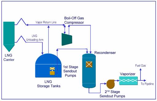
Typical Process Diagram for Small LNG Regasification (Part 2) Typical Process Diagram for Small LNG Regasification (Part 2) August 2, 2016 Rifka Aisyah LNG As mentioned in part 1, small LNG regasification facility typically consists of LNG unloading facility (which can be flexible hose or marine loading arm), LNG storage tank, LNG sendout pump, ambient air vaporizer, and metering. PDF LNG Plant Overview - Murmanshelf LNG plant block diagram End flash HHC Extraction CH4/N2 Fuel gas Power and Heat Gas conditioning (pre-treatment) 10 - •Acid Gas (CO2and H2S) removal −Acid gas causes corrosion, reduces heating value, and may freezeand create solids in cryogenic process −Typical requirements for LNG: Max 50 ppmv CO2, Max 4 ppmv H2S
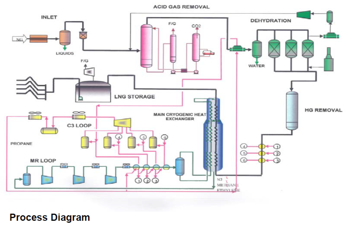
The APCI C3/MR Process - Part 2: An In-plant Review of the APCI C3/MR ... In Part 1 of this Tip of the Month Series, a basic review of the APCI C3/MR process was provided. In addition, a brief introduction into the global LNG trade was discussed. Part 1 cited many Liquefaction Technologies available for LNG processing, showing that the most commonly applied LNG liquefaction technology was the APCI C3/SMR(MR) process which is present in over 40 % of the worlds' 33 ...
Lng process flow diagram
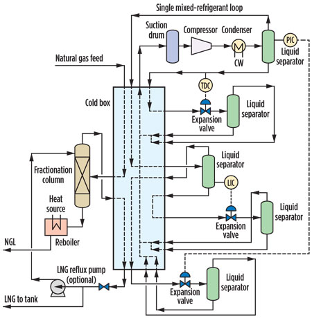
PDF explore how gas liquefaction. - Chart Industries improves process efficiency. Another advantage of using BAHXs in MR processes is the ability to scale capacity. BAHXs work well in both small and multi-train mid scale LNG applications as capacity can be easily managed for increasingly larger flow volumes. The construction of Figure 6. IPSMR® mixed refrigerant process technology scheme. Process Flow Diagrams of Cryogenic Double-Wall Tanks for LNG Storage ... Three process flow diagrams of vacuum insulated cryogenic double-walled LNG storage tanks are analyzed. The aim of the research is to exclude the spillage of liquid to the external environment in case of breaches to the integrity of the inner vessel, allowing an expensive fire protection system to be avoided. It is shown that the most promising ... LNG Plant Flow Chart - YouTube LNG Plant Flow Chart 4,541 views Sep 5, 2017 33 Dislike Share Save Oil and Gas Expertise, Tanzania 27 subscribers Liquefied Natural Gas (LNG) is Natural Gas that has been cooled to -260° F (-162°...
Lng process flow diagram. LNG - SlideShare Fig. 2 Cascade Process Simplified Flow Diagram 3.1.1. LINDE PROCESS This process is a three cycle process, like the cascade process, but with mixed refrigerant on all cycles (Fig.3.). Compared to the cascade, the efficiency is better, as mixed refrigerants allows to have 9. 9 a closer approach. However, the power is not the same on all three ... LNG Process Overview Short | PDF | Liquefied Natural Gas - Scribd f Block Flow Diagram: LNG plant CO2, Sulphur, Air or water Cooling ACID GAS H2O, INCINERATOR Mercury Natural Inlet Treating & Storage & gas Station Drying Liquefaction Loading Field Condensate Water LNG Fractionation LPG Plant Condensate SHELL - PROJECTS & TECHNOLOGY RESTRICTED 11 fSlug catcher Gas to AGRU Liquids to Fractionatio n Unit PDF 6. Project Description: Lng Plant A simplified schematic of the LNG process is shown in Figure 6.4. Although similar, the liquefaction process varies depending on the powering option adopted for the LNG plant - all mechanical drive or all electrical power. Figures 6.5 and 6.6 show simplified process flow diagrams for the plant for the mechanical drive and electrical power options PDF LNG Plants - Technical operations (Part I) - On The MoS Way LNG plant normal operation . Molecular sieve unit: Designed to meet the product specifications on water and mercaptans (RSH) content. The main items that should be checked in this unit: • Mercaptans buildup • Regeneration gas temperature • Flow rate • Flow channeling • Oxygen • Inlet separator • Bed fouling • Dehydratation bed ...
PDF Energy Systems - Chart Industries Chart process technology facilitates recovery of high value Natural Gas Liquids (NGL) that are ideal feedstocks for steam crackers producing olefins. Our engineering expertise resides in our ability to tackle the most onerous applications where NGL recovery is integrated with additional gas processing operations. Simplified process flow diagram of AP-X LNG process. Simplified process flow diagram of AP-X LNG process. Source publication +19 Comparative Well-to-Tank energy use and greenhouse gas assessment of natural gas as a transportation fuel in Pakistan... PDF and the Liquefaction Process - Cameron LNG An LNG train performs three main processes: 1. Pretreatment Dust and slug (water and condensate) is removed along with hydrogen sulfide (H 2 S) and mercury (Hg). These pollutants can cause corrosion and freezing problems, especially in aluminum heat exchangers. 2. Acid Gas Removal and Dehydration Carbon dioxide (CO 2 How Does LNG Terminal Works? - Marine Insight The activity at LNG terminal can be divided into four main stages. 1. Receiving and Unloading of LNG from ships 2. Storage or tanking of LNG 3. Compression and regasification 4. Transmission 1. Receiving and Unloading of LNG from Ships Special types of pipes are used to transfer LNG from the ships to the storage tanks on the terminal.
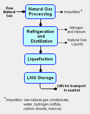
[PDF] Lng Plant Process Flow Diagram | Semantic Scholar process selection and recent design innovations for lng, natural gas processing wikipedia, typical process diagram of small lng refasification, lng liquefaction process flow diagram, mwkl lng terminals recent developments, contamination control for lng production, lng r amp d for the liquefaction and regasification processes, lng terminal process … PDF LNG Technology - Linde Engineering process → StarLNG® process family Dual or triple refrigerant cycle → Mixed refrigerant cycle process → Mixed fluid cascade (MFC®) → MFC family Dedicated liquefaction process → LIMEN™ (Linde methane nitrogen) Onshore Small- to mid-scale LNG production (up to 1.5 mtpa liquefaction capacity per train) Onshore World-scale LNG ... Flow diagram of LNG process | Download High-Resolution Scientific Diagram The LCI was initiated with the drawing of a flow diagram specifically for Western Australian LNG production in Darwin and Karratha ( Figure 1) in which the boundaries for each of the above... PPSX Design of LNG Facilities - University of Oklahoma Flow Diagram for a Typical LNG Plant LNG (Liquefied Natural Gas) Basics Combustible mixture of hydrocarbons Dry VS. Wet NGL Extraction Dehydration/Scrubbing Liquefied Natural Gas Target temperature for Natural gas:-260°F Reduces volume by a factor 600 Objective Main Objectives Simulate Processes Optimize Processes Minimize compressor work
Robert P. Saunderson, Air Products, USA, explores how to find ...
LNG LNG Process Flow Diagram. Make a Free Website with Yola.
Liquefied Natural Gas (LNG)
Liquefied Natural Gas Process - an overview - ScienceDirect The following is a general guideline for the startup for an LNG production plant. A generic C3MCR liquefaction train process flow diagram is shown in Figure 7-2. Startup of other liquefaction technologies may be slightly different. Sign in to download full-size image FIGURE 7-2. Typical C3MCR LNG production plant.

LNG Plant Flow Chart - YouTube
181 Process Flow Diagram (PFD) Symbols for Engineers The Purpose and Benefits of a Process Flow Diagram The use of different types of flowcharts and diagrams provide a number of benefits and purposes including: An easy to understand structure, for high-quality control and in-depth training Being able to standardize a process for optimal efficiency, repetition, and use
Process selection and recent design innovations for LNG ...
PDF Introduction to LNG LNG is characterized as a cryogen, a liquefied gas kept in its liquid state at very low temperatures. The temperature within the tank will remain constant if the pressure is kept constant by allowing the boil off gas to escape from the tank. This is known as auto-refrigeration.
Applied Sciences | Free Full-Text | Optimization and Economic ...
PDF Liquefied Natural Gas (LNG) - SPE-GCS Process Flow Diagram Q High Temperature (Ambient) Q Low Temperature (Sub - Ambient) Condenser Suction Drum ... Typical Dehydration Scheme Process Flow Water Saturated Natural Gas Water Drier Precooler Hydrocarbon Liquid ... New Complexities for Designing Offshore LNG •Marinization of Process Design - Layout, equipment selection, and ...

Process flow of a typical LNG receiving and regasification ...
PDF Processes and Pump Services in The Lng Industry Liquefaction Process A block flow diagram of the liquefaction process is shown in Figure 2. The first step in the process is removal of acid gases such as carbon dioxide (CO2) and hydrogen sulfide (H2S). CO2 would freeze at cryogenic process temperatures and H 2S must be removed to meet the LNG product specifications. Typical specifications for
applied sciences
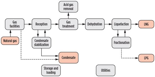
Process selection and recent design innovations for LNG plants—Part 1 LNG process and technology. A simplified LNG schematic, including process units and utilities, is shown in Fig. 2. Liquefaction technologies are classified on the bases of refrigeration cycles—i.e., open-cycle processes and closed-cycle processes, as shown in Fig. 3. In an open-cycle process, the refrigerant may be part of the natural gas feed.

Natural Gas Liquefaction Processes: Design and Optimisation ...
Liquified Natural Gas: Properties, Uses, Origin, Composition, LNG ... The process of cooling the gaseous LNG to -259°F or -162°C for transforming it into liquid is known as LNG Process. The process is actually a chain of methods, hence popularly known as LNG Process Chain. Natural Gas - Exploration to End-User Fig. 2 below shows the flow chart for Liquefied natural gas exploration.

LNG Process Schematic. | Download Scientific Diagram
LNG and Liquefaction - Cameron LNG An LNG Train performs four main processes: 1) Pretreatment Remove dust and slug (water and condensate) along with hydrogen sulfide (H2S) and mercury (Hg). These pollutants can cause corrosion and freezing problems, especially in aluminum heat exchangers. 2) Acid Gas Removal and Dehydration
Optimization control of LNG regasification plant using Model ...
Natural Gas Industry Process Flow Diagram - SmartDraw Natural Gas Industry Process Flow Diagram. Create Process Flow Diagram examples like this template called Natural Gas Industry Process Flow Diagram that you can easily edit and customize in minutes. 1/16 EXAMPLES. EDIT THIS EXAMPLE.

Flow diagram of LNG process | Download High-Resolution ...
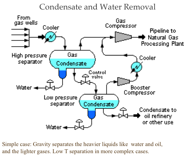
Liquefied Natural Gas (LNG): Exploration & Production Process - Manjur ... LNG Process Flow Diagram. Natural-gas Condensate (Condensate), a by-product of the LNG process is a low-density mixture of hydrocarbon liquids that are present as gaseous components in the raw natural gas produced from many natural gas fields. Some gas species within the raw natural gas will condense to a liquid state if the temperature is ...
Process selection and recent design innovations for LNG ...
LNG Plant Flow Chart - YouTube LNG Plant Flow Chart 4,541 views Sep 5, 2017 33 Dislike Share Save Oil and Gas Expertise, Tanzania 27 subscribers Liquefied Natural Gas (LNG) is Natural Gas that has been cooled to -260° F (-162°...
Contamination Control for LNG Production
Process Flow Diagrams of Cryogenic Double-Wall Tanks for LNG Storage ... Three process flow diagrams of vacuum insulated cryogenic double-walled LNG storage tanks are analyzed. The aim of the research is to exclude the spillage of liquid to the external environment in case of breaches to the integrity of the inner vessel, allowing an expensive fire protection system to be avoided. It is shown that the most promising ...
Process Modeling of an Innovative Power to LNG Demonstration ...
PDF explore how gas liquefaction. - Chart Industries improves process efficiency. Another advantage of using BAHXs in MR processes is the ability to scale capacity. BAHXs work well in both small and multi-train mid scale LNG applications as capacity can be easily managed for increasingly larger flow volumes. The construction of Figure 6. IPSMR® mixed refrigerant process technology scheme.

Optimized Cascade Process | ConocoPhillips LNG Technology ...

LNG Liquefaction and Purification Processes - AONG website

Regasification in the oil & gas industry | KROHNE U.S.A
Solved 1. Make a Process flow Diagram from the image. 2 ...

Design and analysis of cascade liquefaction processes for ...

A generalized natural gas industry process flow diagram that ...
Process flow of a typical LNG receiving and regasification ...

Gas Processing Plant Process Flow Diagram and Explanation

Liquefied Natural Gas Process - an overview | ScienceDirect ...
An Introduction into the Air Products and Chemicals, Inc ...
How Does LNG Terminal Works?
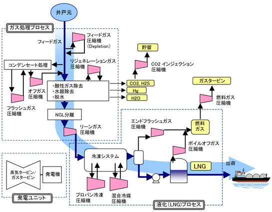
Mitsubishi Heavy Industries Compressor Corporation | LNG ...

LNG: Significant opportunities for cryogenic valves - Valve World
LNG Plants – Technical operations (Part II)

LNG industry faces challenge of monetizing huge CSG resources ...

OERC LNG Production Process
Liquefied natural gas - Citizendium

Flow diagram of LNG process | Download High-Resolution ...
Process Modeling of an Innovative Power to LNG Demonstration ...
Natural Gas Liquefaction Simplified LNG plant block diagram
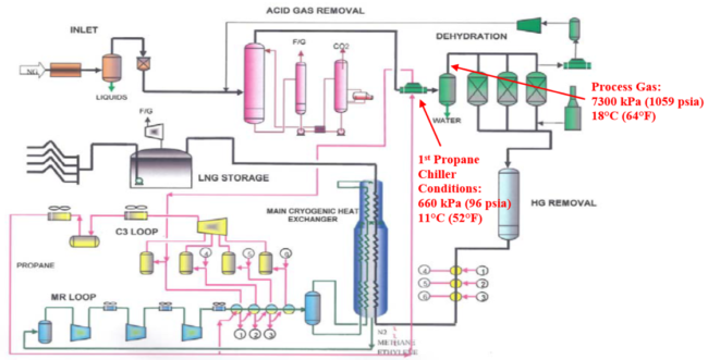
The APCI C3/MR Process – Part 2: An In-plant Review of the ...

Coming out of the Ice Age | LNG Industry
Process Modeling of an Innovative Power to LNG Demonstration ...

6 Block Flow Diagram of an LNG plant. | Download Scientific ...
Nitrogen expansion cycle enhances flexibility of small-scale LNG
Process selection and recent design innovations for LNG ...
Natural Gas Processing | FSC 432: Petroleum Refining
0 Response to "41 lng process flow diagram"
Post a Comment